

 English
  русский
  عربى
عربى Content
The Fundamentals of Auger Boring Technology
Auger boring, often referred to as "jack and bore," is a premier trenchless method used to install steel casing pipes underground without disturbing the surface environment. The Auger Boring Machine (ABM) functions by rotating a flighted auger inside a steel casing while simultaneously jacking the casing into the soil using hydraulic rams. This dual action allows for the excavation of earth at the cutting head and the immediate transport of spoil back to the machine's entry pit. It is particularly effective for installations under railways, highways, and existing structures where open-cut trenching is impossible or cost-prohibitive.
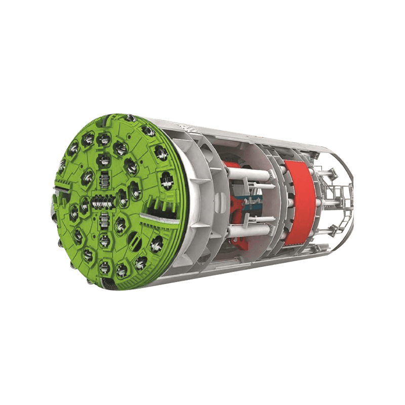
Core Components and Mechanical Anatomy
To achieve precision in horizontal boring, several specialized components must work in perfect synchronization. The efficiency of the operation depends largely on the compatibility of the machine's torque and thrust capabilities with the geological conditions of the site.
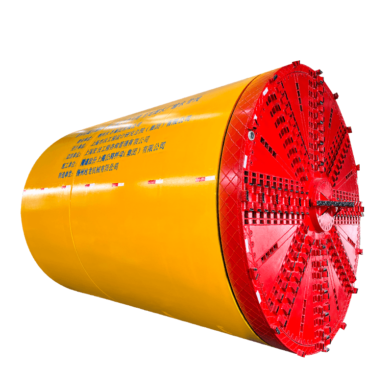
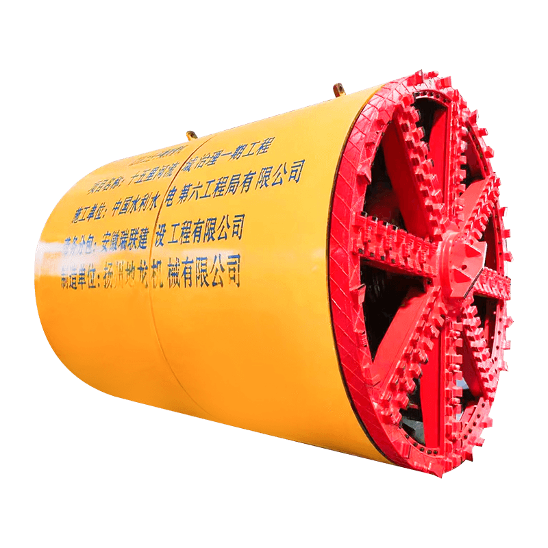
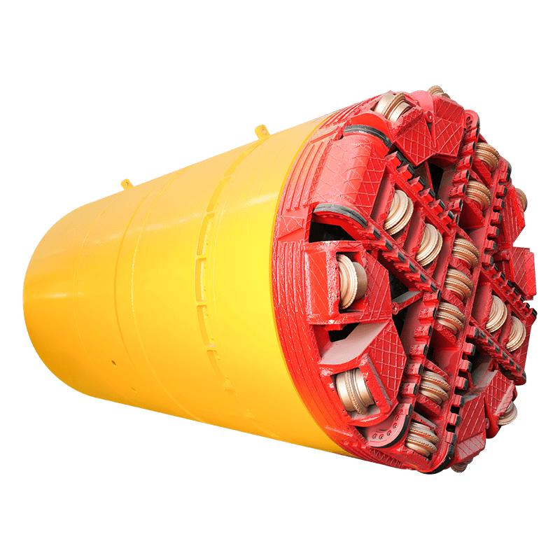
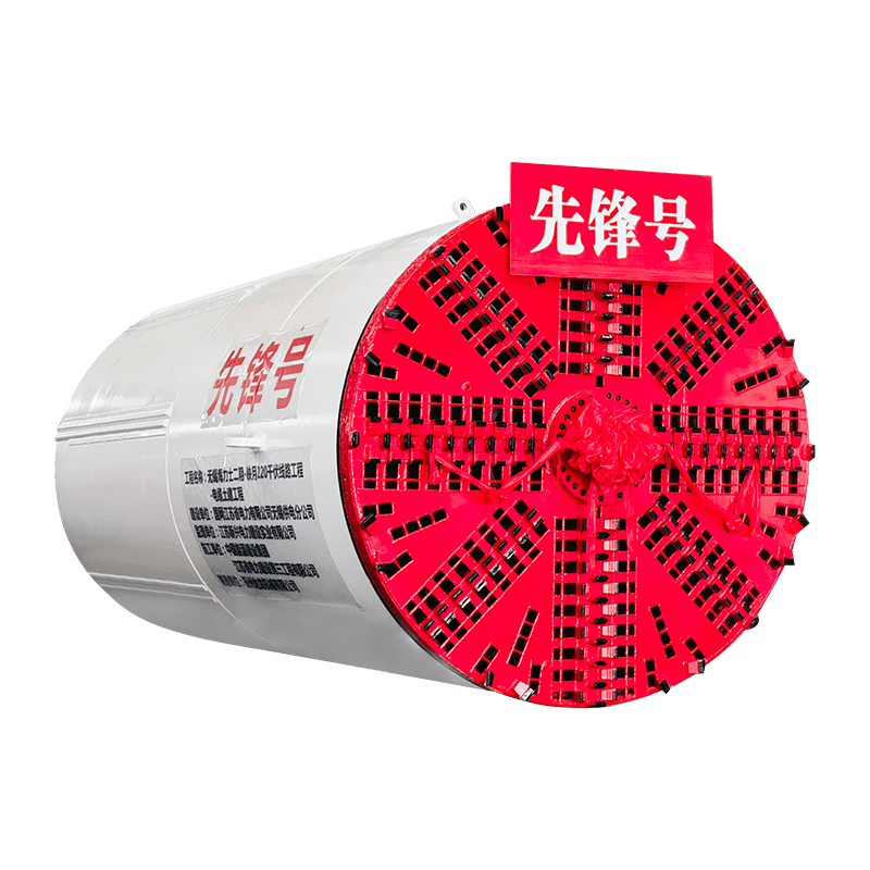
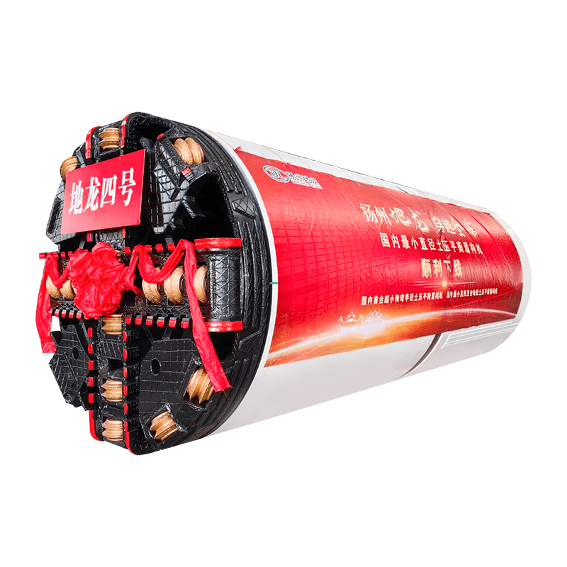
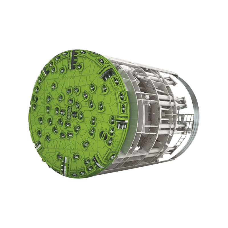
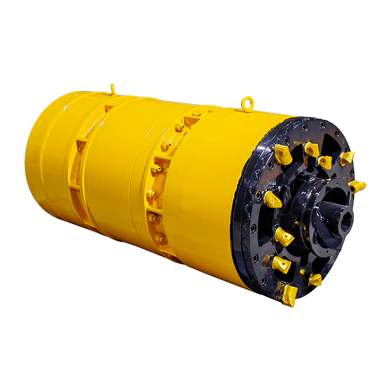
The Cutting Head and Auger Flights
The cutting head is the "business end" of the machine, designed to break up soil and rock. Behind it, the auger flights act as a screw conveyor, moving the excavated material through the casing to the master pusher. Different soil types—ranging from loose sand to hard clay or shale—require specific head configurations, such as wing cutters or rock heads with carbide bits.
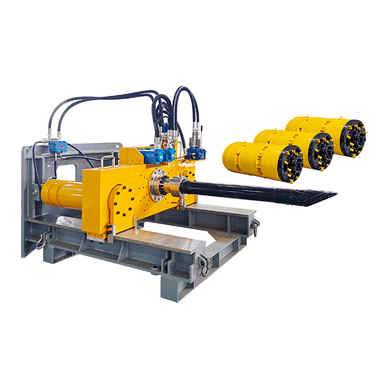
The Power Unit and Hydraulic System
Modern ABMs are powered by high-torque diesel engines that drive the hydraulic pumps. These pumps provide the necessary force for the thrust cylinders to push the casing forward and the rotational power to spin the augers. Precise control over these hydraulic pressures is vital to prevent "heaving" (lifting the ground above) or "subsidence" (ground sinking).
Operational Comparison: Standard vs. Guided Boring
While basic auger boring is effective for short distances, increased accuracy over long runs often requires guided systems. The following table highlights the differences between traditional methods and modern guided technologies.
| Feature | Standard Auger Boring | Guided Boring (GAB) |
| Steering Capability | Limited/Passive | Active Pilot Tube Control |
| Typical Accuracy | +/- 1% of Bore Length | High Precision (Grade Specific) |
| Ideal Application | Culverts & Large Casings | Gravity Sewers & Tight Corridors |
Key Technical Specifications for Equipment Selection
Selecting the right Auger Boring Machine requires a detailed analysis of the project's engineering specs. Overloading a machine can lead to mechanical failure, while an undersized unit will stall in dense soil conditions. Engineers must prioritize the following variables:
- Maximum Thrust Force: Measured in tons, this determines the machine's ability to overcome skin friction on the casing.
- Rotational Torque: Essential for breaking through tough ground and spinning large-diameter augers.
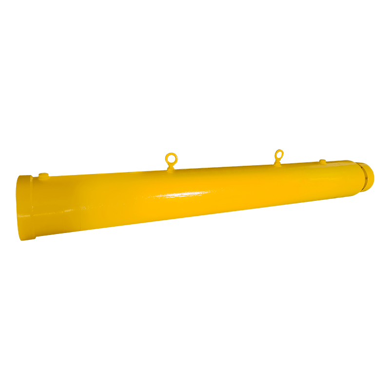
- Casing Range: The span of pipe diameters the machine can accommodate (e.g., 12 inches to 72 inches).
- Track Length: Defines the setup footprint in the entry pit and the length of casing sections that can be used.
Best Practices for Site Safety and Execution
Safety is paramount when operating heavy machinery in confined pit spaces. Proper shoring of the entry and exit pits is the first line of defense against cave-ins. Operators must also ensure that the machine is perfectly leveled on its track system before beginning the bore, as even a minor misalignment at the start can result in a significant deviation at the exit point. Constant monitoring of the spoil discharge is also necessary; if the volume of soil coming out exceeds the volume of the pipe being installed, it may indicate a void is forming above the casing, necessitating an immediate stop to evaluate ground stability.


