


 English
  русский
  عربى
عربى Content
- 1 What Is a Rock Pipe Jacking Machine and Where Is It Used?
- 2 How a Rock Pipe Jacking System Works
- 3 Key Components of a Rock Pipe Jacking Machine
- 4 Rock Pipe Jacking Machine Types by Diameter and Ground Condition
- 5 Geotechnical Investigation Requirements for Rock Pipe Jacking
- 6 Pipe Materials Used in Rock Pipe Jacking Operations
- 7 Factors Affecting Advance Rate and Project Cost in Rock Pipe Jacking
- 8 Selecting the Right Rock Pipe Jacking Machine for Your Project
What Is a Rock Pipe Jacking Machine and Where Is It Used?
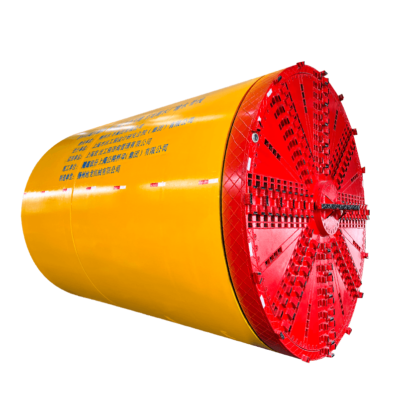
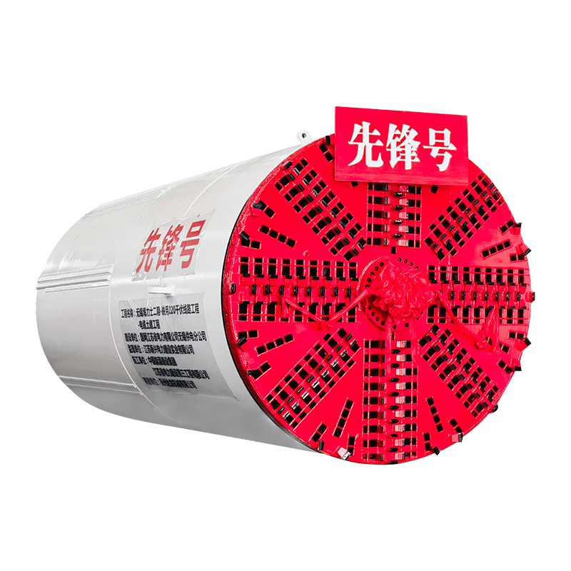
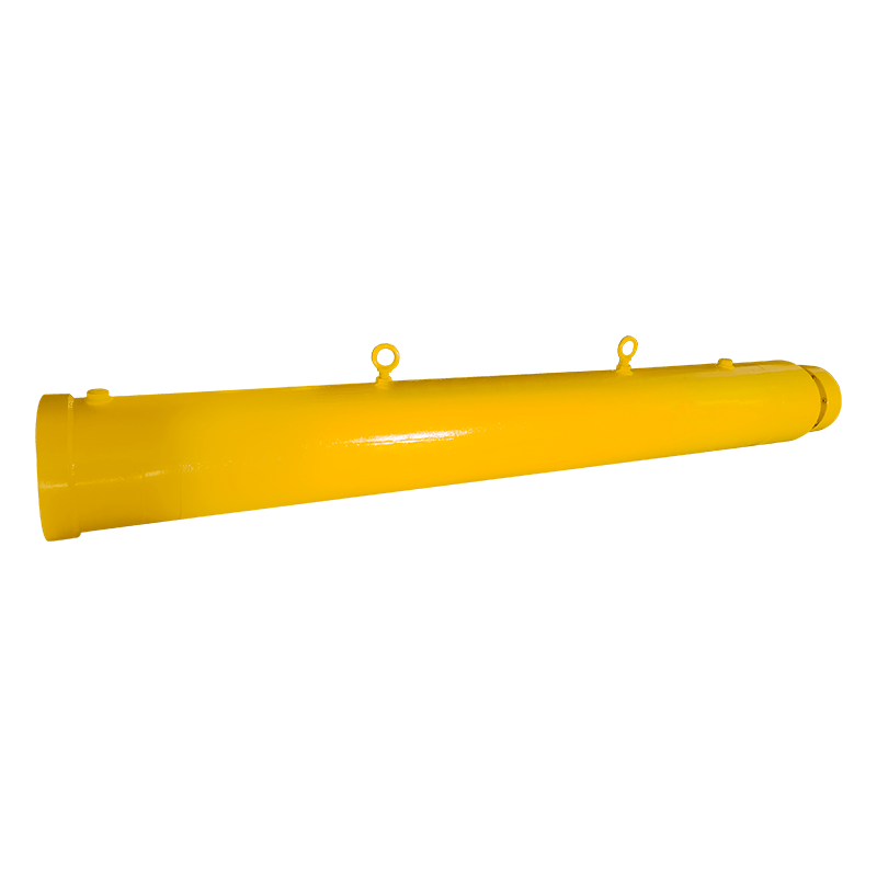
A rock pipe jacking machine is a specialized trenchless construction system engineered to bore through hard rock formations and simultaneously install pipeline infrastructure without requiring open-cut excavation from the surface. Unlike conventional pipe jacking equipment designed for soft soil and mixed-face conditions, a rock pipe jacking machine incorporates a rock-specific cutting head — typically fitted with disc cutters, drag bits, or tricone roller cutters — capable of fracturing and excavating rock with unconfined compressive strengths (UCS) ranging from 30 MPa in moderately hard sandstone up to 300 MPa or higher in granite, quartzite, and basalt formations. The jacking system pushes reinforced concrete or steel pipe sections through the bored annulus as excavation advances, building the permanent pipeline behind the machine in a continuous operation.
Rock pipe jacking machines — also referred to as rock microtunneling machines, hard rock pipe jacking systems, or rock MTBM (microtunnel boring machines) — are deployed across a wide range of underground utility and infrastructure applications where surface disruption must be minimized and geological conditions preclude the use of conventional soil pipe jacking or open-cut methods. Primary applications include gravity sewer mains beneath busy urban streets, highways, and railways; water transmission mains and raw water intake tunnels through bedrock; gas and telecommunications duct crossings under sensitive environmental zones; stormwater culverts through rock ridges; and outfall structures from treatment plants where pipeline alignment must pass through competent rock to reach the receiving water body. The ability to install pipelines through solid rock without surface disruption represents one of the most significant capabilities in modern trenchless engineering.
How a Rock Pipe Jacking System Works
Understanding the operational sequence of a rock pipe jacking system provides the foundation for evaluating equipment selection, ground investigation requirements, and construction planning. The process integrates surface infrastructure, launch shaft preparation, machine operation, and continuous pipe installation into a coordinated construction workflow.
Launch Shaft Preparation and Machine Setup
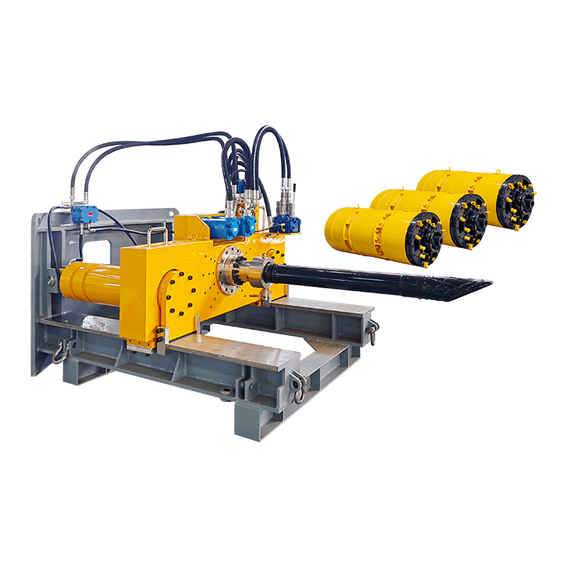
Every rock pipe jacking operation begins with the construction of a launch shaft — a vertically excavated pit of sufficient dimensions to lower the pipe jacking machine, assemble the main jacking frame, and stage pipe sections for installation. The launch shaft must be sized to accommodate the full length of the longest pipe section being installed, typically 1,000 to 3,000 mm, plus the machine body length and jacking frame stroke. A reinforced concrete thrust wall is cast at the rear of the shaft to distribute the substantial jacking reaction forces — which can reach several thousand kilonewtons in long-drive rock jacking operations — back into the surrounding ground. The main jacking frame, consisting of the hydraulic jacking cylinders, pipe cradle guides, and control systems, is installed and aligned to the design pipe gradient and azimuth using precision laser guidance equipment before any boring commences.
Rock Cutting Head Operation and Spoil Removal
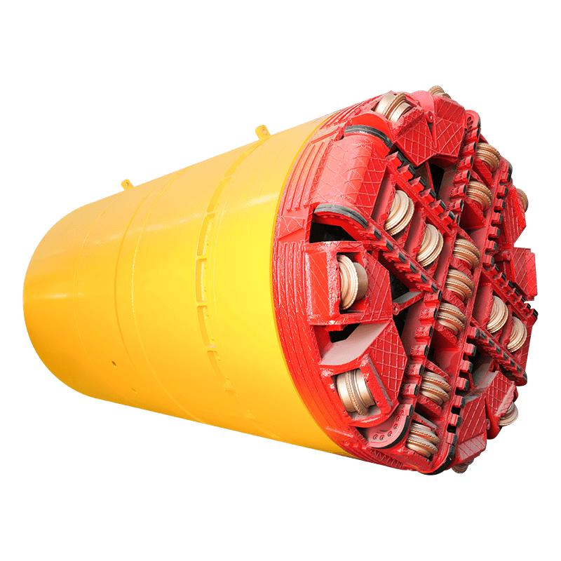
At the front of the rock pipe jacking machine, the cutting head rotates under hydraulic drive torque while being advanced against the rock face by the jacking force transmitted through the pipe string from the main jacking frame at the launch shaft. In disc cutter configurations, hardened steel disc rings roll against the rock face under high normal force, creating tensile fracture chips between adjacent cutter tracks — the same rock-breaking principle used in full-face tunnel boring machines. In drag bit configurations, polycrystalline diamond compact (PDC) or carbide-tipped drag cutters shear and scrape rock as the head rotates, generating finer muck than disc cutters and operating more efficiently in moderately hard and abrasive formations below approximately 100 MPa UCS. Rock cuttings and fines generated at the cutting face are flushed rearward through the machine body by a slurry circulation system using bentonite or water-based slurry pumped under pressure to the cutting face and returned to the surface through a separate slurry return line carrying excavated material in suspension. At the surface, a separation plant processes the return slurry, removing rock cuttings and recirculating clean slurry back to the machine.
Pipe Installation and Intermediate Jacking Stations
As the rock cutting head advances, each completed boring stroke of the main jacking cylinders creates space at the rear of the shaft for a new pipe section to be lowered, positioned on the cradle guides, and connected to the rear of the growing pipe string using steel-collar or spigot-and-socket joints. The jacking cylinders then retract, engage the new pipe section, and advance the entire pipe string — including the rock machine at its leading end — by one pipe length. This cycle of boring, retracting, and installing new pipe sections continues until the machine reaches the reception shaft at the far end of the drive. For long drives where the accumulated skin friction between the outer pipe surface and the surrounding rock borehole becomes too large for the main jacking frame to overcome alone, intermediate jacking stations (IJS) — hydraulic cylinder assemblies installed within the pipe string at predetermined intervals — provide additional distributed jacking force to maintain forward progress without exceeding the structural compressive capacity of the pipe sections.
Laser Guidance and Steering Control
Maintaining accurate alignment of the pipe string to the design grade and azimuth throughout the drive is one of the most critical operational challenges in rock pipe jacking. A laser beam projected from the launch shaft along the design alignment illuminates a target mounted on the machine body, with the target position deviation from the laser beam centerline displayed on the surface control console in real time. The operator corrects alignment deviations by differentially adjusting the pressure on the machine's steering cylinders — hydraulic rams that deflect the articulated front cutting head section relative to the trailing shield body. In hard rock formations with highly variable joint spacing and orientation, the machine can be deflected from design alignment by anisotropic ground reaction forces at the cutting face, requiring proactive steering correction before deviations accumulate beyond acceptable tolerance limits — typically ±25 to ±50 mm from design alignment for sewer gravity pipeline installations.
Key Components of a Rock Pipe Jacking Machine
A rock pipe jacking system comprises multiple integrated subsystems that must function reliably in continuous operation to achieve the required advance rates and installation quality. Each major component contributes a distinct function to the overall system performance, and understanding their roles is essential for equipment evaluation, maintenance planning, and troubleshooting during construction.
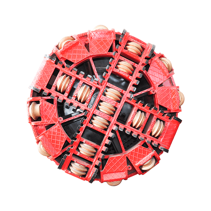
Cutting Head and Cutter Tooling
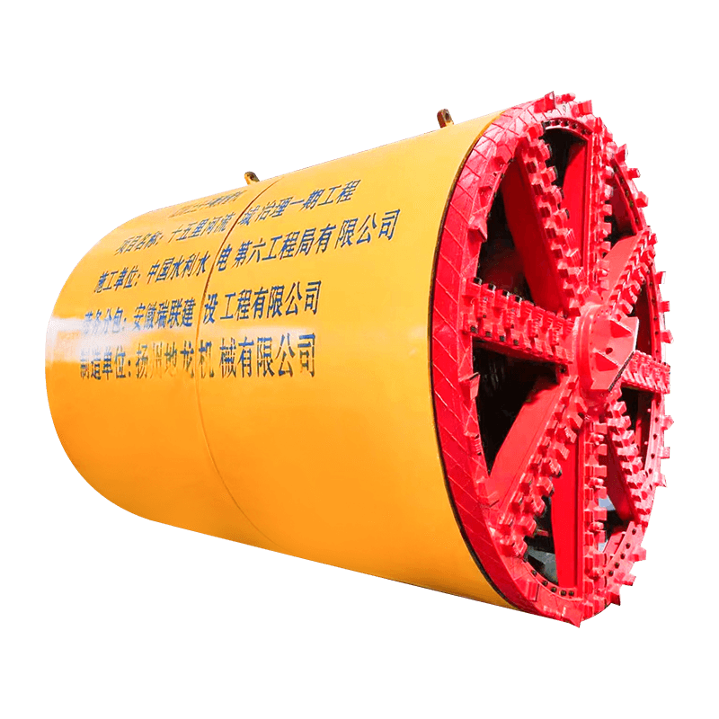
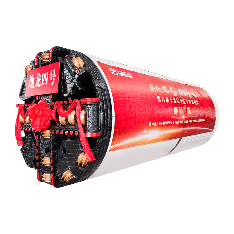
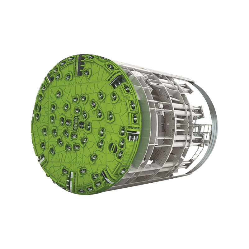
The cutting head is the most application-critical component of the rock pipe jacking machine, and its design must be specifically matched to the rock type, strength, abrasivity, and joint structure identified in the geotechnical investigation. For hard, massive rock formations above 80 MPa UCS, disc cutter heads with 17-inch or 19-inch diameter hardened steel disc rings mounted in forged steel housings provide the most effective and durable cutting action. Disc cutter spacing, typically 70 to 90 mm between adjacent cutter tracks, is optimized for the specific rock type to maximize chip size and cutting efficiency. For softer rock and mixed-face conditions involving both rock and soil, combination heads fitted with disc cutters in the rock zones and drag bits or carbide bucket teeth in the soil zones provide versatility for variable geological profiles. Cutter wear monitoring — either through direct inspection during planned maintenance interventions or via continuous torque and advance rate data analysis — is critical because worn or broken cutters that are not replaced promptly dramatically reduce advance rates and can result in cutting head structural damage.
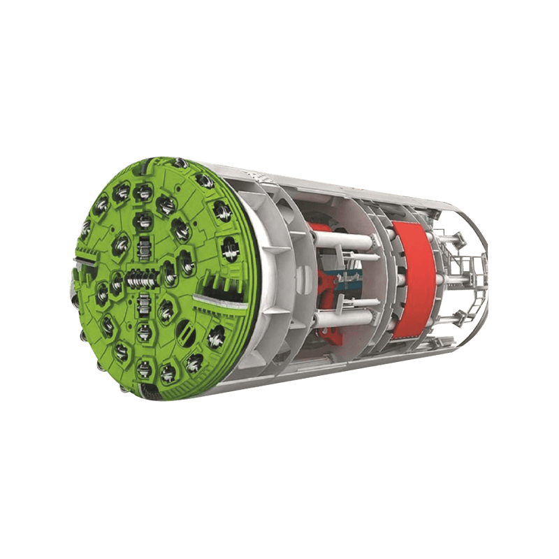
Main Drive Unit and Hydraulic System
The main drive unit rotates the cutting head through a high-torque hydraulic motor and planetary gearbox assembly housed within the machine shield. Drive torque requirements for rock pipe jacking machines are substantially higher than for soil machines of equivalent diameter — a 1,500 mm diameter rock microtunneling machine operating in 150 MPa granite may require continuous drive torques of 200 to 400 kN·m, compared to 50 to 100 kN·m for a soil machine of the same size. The hydraulic power pack on the surface supplies high-pressure hydraulic fluid to both the drive motor and the steering cylinders through high-pressure hose bundles routed through the bore alongside the slurry supply and return lines, electrical cables, and guidance system conduits. Hydraulic system cleanliness — maintained through regular filter changes and careful fluid management — is essential for preventing valve and motor damage in the high-pressure circuits that operate continuously during boring.
Slurry Circulation System
The slurry system is the circulatory system of the rock pipe jacking operation, performing the essential functions of transporting excavated cuttings from the cutting face to the surface separation plant, providing face support pressure to prevent uncontrolled inflow of groundwater or unstable material at the cutting face, and lubricating the annular space between the outer pipe surface and the bored rock profile to reduce jacking friction. The slurry supply pump, typically a centrifugal or progressive cavity type installed on the surface, pushes fresh slurry under pressure through the supply line to the cutting head. The slurry return pump — a more demanding application because it must handle an abrasive rock-particle-laden slurry — is usually a centrifugal pump sized to maintain the required return flow velocity above the settling velocity of the coarsest rock particle fraction being transported. Maintaining the correct slurry density, viscosity, and pH within design parameters throughout the drive is the responsibility of the slurry engineer and requires regular sampling and testing of both the supply and return streams.
Main Jacking Frame and Intermediate Jacking Stations
The main jacking frame installed in the launch shaft provides the primary thrust force to advance the pipe string and machine through the rock. It consists of a structural steel frame carrying two or four hydraulic cylinders with strokes of 1,000 to 2,000 mm, a pipe cradle guide system to maintain alignment of incoming pipe sections, and a spreading beam or jacking ring that distributes the cylinder force uniformly around the circumference of the pipe end to prevent localized stress concentrations that could crack the pipe. Intermediate jacking stations embedded within the pipe string at intervals of 100 to 300 m, depending on ground friction conditions, consist of thin hydraulic cylinder cassettes that expand within a purpose-built enlarged pipe joint, pushing the forward pipe string against the reaction of the trailing string. After the drive is complete, the IJS void is grouted and the cylinders removed or left in place depending on system design, leaving the pipeline in its final installed configuration.
Rock Pipe Jacking Machine Types by Diameter and Ground Condition
Rock pipe jacking machines are manufactured across a wide range of diameters and cutting head configurations to address the full spectrum of pipeline sizes and geological conditions encountered in underground construction. The following table summarizes the principal machine categories, their operational characteristics, and their most common application domains.
| Machine Category | Pipe Diameter Range | Rock UCS Range | Cutting Head Type | Typical Application |
| Small-Bore Rock MTBM | 250–600 mm | Up to 150 MPa | PDC drag bits / mini disc cutters | Service ducts, gas mains, telecommunications |
| Medium-Bore Rock MTBM | 600–1,200 mm | Up to 200 MPa | Disc cutters / combination head | Gravity sewers, water mains, stormwater |
| Large-Bore Rock Pipe Jacking | 1,200–3,000 mm | Up to 250 MPa | Full-face disc cutter head | Trunk sewers, water transmission, outfalls |
| Ultra-Hard Rock Specialist | 800–2,400 mm | 200–300+ MPa | Heavy-duty disc cutters, high-thrust design | Granite, quartzite, basalt formations |
| Mixed-Face Rock/Soil Machine | 600–2,000 mm | Variable (0–150 MPa) | Combination disc + drag bit head | Variable geology, weathered rock transitions |
Geotechnical Investigation Requirements for Rock Pipe Jacking
No other factor has a greater influence on rock pipe jacking machine selection, cutter tooling specification, and project cost than the quality and completeness of the geotechnical investigation program conducted prior to tender and construction. Rock pipe jacking in inadequately characterized ground is one of the primary causes of project cost overruns, schedule delays, and equipment damage in trenchless construction globally.
Rock Strength and Abrasivity Testing
Unconfined compressive strength (UCS) testing of representative core samples from the proposed drive alignment is the minimum baseline requirement for rock pipe jacking machine selection. UCS values from multiple test specimens should be presented statistically — not just as a single average — to capture the variability that will affect advance rate predictions and cutter consumption estimates. Brazilian tensile strength (BTS) testing complements UCS data by characterizing the rock's tensile fracture behavior, which governs disc cutter chipping efficiency. Rock abrasivity — quantified through the Cerchar Abrasivity Index (CAI) or LCPC abrasivity coefficient — is equally critical because it directly predicts the rate of cutter wear and the frequency of cutter replacement interventions required during the drive. Abrasivity testing on core samples from the actual drive corridor, rather than published values from general geological literature, is essential because abrasivity can vary dramatically within a single rock formation depending on quartz content, grain size, and degree of weathering.
Rock Mass Characterization
Beyond intact rock strength, the structural characteristics of the rock mass — joint spacing, joint orientation, degree of weathering, presence of fault zones, and groundwater conditions — profoundly affect machine performance and operational risk. Closely jointed or heavily fractured rock masses can cause cutting head instability and face collapse even when the intact rock strength is very high. Major fault zones or shear zones crossing the drive alignment present the risk of sudden transitions from competent hard rock to fault gouge and crushed material that may require dramatically different machine operating parameters. Hydrogeological characterization — including groundwater pressure measurements, permeability testing, and assessment of potential inflows — is essential for designing the face support pressure parameters and slurry system capacity, and for evaluating the risk of water inflow events during cutter inspection and replacement operations that require the machine face to be depressurized.
Pipe Materials Used in Rock Pipe Jacking Operations
The pipe sections installed behind a rock pipe jacking machine serve dual roles: they form the permanent pipeline infrastructure and they act as the structural column through which all jacking forces are transmitted from the main jacking frame and intermediate jacking stations to the cutting head at the drive face. The pipe material must therefore satisfy both the long-term service requirements of the pipeline and the short-term structural demands of the installation process.
- Reinforced Concrete Jacking Pipe (RCJP): Specially manufactured reinforced concrete pipe conforming to ASTM C1628, ISO 9664, or equivalent standards is the most widely used pipe material for rock pipe jacking in diameters above 600 mm. RCJP is produced with precisely machined steel end rings that provide the bearing surface for jacking force transmission and ensure uniform load distribution around the pipe circumference. Concrete compressive strength for jacking pipe typically meets or exceeds 60 MPa to resist the high contact stresses at pipe joints under jacking load. The pipe's smooth interior invert surface supports slurry flow during construction and provides the hydraulic performance required for gravity sewer applications after commissioning.
- Vitrified Clay Jacking Pipe: Vitrified clay pipe (VCP) offers outstanding chemical resistance to aggressive sewer gases, industrial effluents, and acidic groundwater, making it the material of choice for gravity sewer applications in highly corrosive environments where concrete pipe degradation is a concern. VCP jacking pipe is manufactured with precision-ground steel collar joints and achieves allowable jacking loads of 2,000 to 8,000 kN depending on pipe diameter and wall thickness classification.
- Steel Jacking Pipe: Welded steel pipe with external corrosion protection and internal lining is used for rock pipe jacking installations where the pipeline will operate under internal pressure — water transmission mains, force mains, and gas pipelines — or where the bore profile requires very tight positional tolerances that benefit from the higher structural stiffness and thinner wall section of steel pipe. Steel pipe sections are joined by welding within the launch shaft during installation, which eliminates the joint compression loss associated with concrete and clay pipe joints and reduces friction between the pipe string and the bored rock profile.
- GRP (Glass Reinforced Plastic) Jacking Pipe: GRP jacking pipe provides excellent corrosion resistance, low wall friction, and a smooth interior hydraulic surface in a lightweight product that reduces shaft handling requirements. GRP jacking pipe is widely specified for sewer applications in corrosive ground conditions and is available in diameters from 300 mm to 2,400 mm with allowable jacking loads certified through independent structural testing programs.
Factors Affecting Advance Rate and Project Cost in Rock Pipe Jacking
The advance rate achieved by a rock pipe jacking machine — measured in meters of completed pipeline installed per shift or per day — is the primary driver of project schedule and unit cost, and it is the most complex parameter to predict accurately at the tender stage due to the many interacting variables that influence it in practice.
Rock Strength and Cutter Wear Rate
Advance rate decreases as rock UCS and abrasivity increase, because harder and more abrasive rock requires more cutting energy per unit volume excavated and wears cutter tooling more rapidly. In granitic rock with CAI values above 4.0, individual disc cutter rings may require replacement after as little as 20 to 50 meters of advance, requiring the drive to be halted for cutter inspection and replacement at frequent intervals. Each cutter change intervention involves depressurizing the face, entering the machine from the launch shaft — or through man-entry ports in larger diameter machines — replacing worn cutters, and resealing the machine before resuming boring. This non-productive time for cutter maintenance can account for 40 to 60 percent of total drive duration in highly abrasive rock conditions, and accurately estimating this component of the schedule is essential for realistic project cost modeling.
Drive Length and Intermediate Jacking Station Planning
As drive length increases, jacking friction accumulates along the pipe string's contact length with the surrounding rock borehole, progressively increasing the total thrust force required to advance the machine. Lubrication of the pipe exterior with bentonite or polymer slurry injected through ports in the pipe wall significantly reduces this friction — effective lubrication can reduce friction coefficients from 0.3–0.5 to 0.1–0.2 — but does not eliminate it entirely. Intermediate jacking stations must be planned and positioned before construction to ensure the pipe column never approaches its allowable compressive load limit. IJS positioning analysis must account for the worst-case combination of maximum face resistance, maximum skin friction, and the structural capacity of the weakest pipe section in the string, including the pipe sections adjacent to IJS cassette locations where cross-sectional area may be reduced.
Groundwater Management and Slurry Control
High groundwater inflows into the bored tunnel profile significantly reduce advance rates by diluting the working slurry below functional density and viscosity thresholds, overloading the slurry separation plant with excess water volume, and creating face stability challenges during cutter maintenance interventions. Pre-excavation ground treatment — including chemical grouting, permeation grouting, or compressed air saturation of the rock mass ahead of the machine — can reduce groundwater inflows to manageable levels in permeable fractured rock zones identified through the geotechnical investigation. Slurry density management requires continuous monitoring and adjustment of bentonite or polymer additions to the supply slurry to maintain face support pressure above groundwater pressure throughout the drive, particularly during any planned stoppages where slurry circulation ceases and passive face support must be maintained by the static slurry column.
Selecting the Right Rock Pipe Jacking Machine for Your Project
Choosing the correct rock pipe jacking machine configuration for a specific project requires systematic evaluation of ground conditions, pipeline geometry, site constraints, and project risk tolerance. The following criteria framework guides equipment selection decisions and helps project owners and contractors identify the key technical requirements that must be addressed in tender specifications and contractor submissions.
- Maximum Rock UCS and Abrasivity: The peak UCS and CAI values from the geotechnical investigation define the minimum cutting head thrust capacity, disc cutter diameter and bearing load rating, and cutter steel grade specification required. A machine specified for 150 MPa rock will be structurally inadequate for a drive that encounters 250 MPa quartzite, regardless of advance rate predictions — structural overload of the cutting head support structure is a severe and expensive failure mode.
- Geological Variability and Mixed-Face Risk: Drives through geologically variable profiles — including transitions between hard rock and weathered zones, boulder fields in soil matrices, or interbedded hard and soft rock layers — require cutting heads designed for mixed-face conditions with both disc cutters and drag bits/bucket teeth, rather than a pure rock disc cutter configuration that cannot handle the soft zones efficiently.
- Drive Length and Maximum Jacking Force: Long drives above 300 m require intermediate jacking station capacity built into the system design from the outset, and the main jacking frame must provide sufficient stroke and force to establish initial drive momentum through the high-resistance rock formation before IJS units take over distributed thrust duties.
- Minimum Overburden and Surface Sensitivity: Shallow drives with limited rock overburden above the machine create risk of face blow-out — uncontrolled escape of pressurized slurry to the surface — and require careful face pressure management and potentially reduced machine advance rates during critical surface-sensitive sections passing beneath infrastructure or waterways.
- Man-Entry vs. Remote Cutter Inspection: Drives in diameters below approximately 900 mm preclude safe human entry to the machine for cutter inspection and replacement, requiring either extended cutter life tooling designed to complete the full drive without intervention, or surface retrieval of the cutting head to the launch shaft for cutter changes. This distinction significantly affects tooling specification, contingency planning, and drive length limitations compared to larger-diameter machines where man-entry cutter maintenance is operationally viable.
- Availability of Local Technical Support: Rock pipe jacking machines are complex precision equipment operating in remote underground environments where equipment failure has disproportionate cost and schedule consequences. Machine manufacturer technical support response time, local spare parts availability, and the depth of the operating contractor's maintenance capability should all be evaluated as risk factors alongside the purely technical performance specifications when selecting equipment for a critical-path underground pipeline project.


