


 English
  русский
  عربى
عربى Content
- 1 What a Pipe Jacking Machine Actually Does
- 2 The Core Components of a Pipe Jacking System
- 3 Types of Pipe Jacking Machines and When Each Is Used
- 4 Ground Conditions and Their Impact on Machine Selection
- 5 Managing Jacking Forces and Using Intermediate Jacking Stations
- 6 Pipe Materials Used in Pipe Jacking Operations
- 7 Key Project Planning Considerations Before Mobilizing a Pipe Jacking Machine
- 8 Common Problems During Pipe Jacking and How Experienced Contractors Handle Them
What a Pipe Jacking Machine Actually Does
A pipe jacking machine is a trenchless construction system that installs underground pipelines by simultaneously boring through soil and pushing prefabricated pipe sections into the excavated tunnel from a surface-level launch pit. The machine cuts at the face of the bore while hydraulic jacks positioned at the rear of the pipe string apply the forward thrust needed to advance both the cutting head and the growing pipe train through the ground. The result is a fully lined pipeline installed at depth, without the need to excavate a continuous open trench along the pipeline route.
This method — also referred to as pipe jacking, pipe ramming in some contexts, or microtunneling when applied to smaller diameter bores with remote-controlled guidance — has become one of the most important techniques in underground utility construction. It is used to install gravity sewer mains, water transmission mains, gas distribution lines, telecommunications ducting, and culverts beneath roads, railways, rivers, runways, and built-up urban areas where open-cut excavation would be impractical, damaging, or prohibited by infrastructure operators and planning authorities.
The pipe jacking machine itself is the cutting and guidance system at the front of the operation — the component that determines bore diameter, soil compatibility, line and grade accuracy, and face support capability. Everything else in a pipe jacking operation — the jacking frame, thrust ring, intermediate jacking stations, lubrication system, and spoil removal arrangement — is configured around the machine's requirements and the specific ground conditions encountered on the project.
The Core Components of a Pipe Jacking System
A complete pipe jacking system is more than just the cutting machine. It is an integrated assembly of mechanical, hydraulic, and guidance systems that must all work together reliably for the operation to advance safely and on line. Understanding each component's role helps contractors and project engineers make better equipment selection decisions and anticipate where problems are most likely to occur.
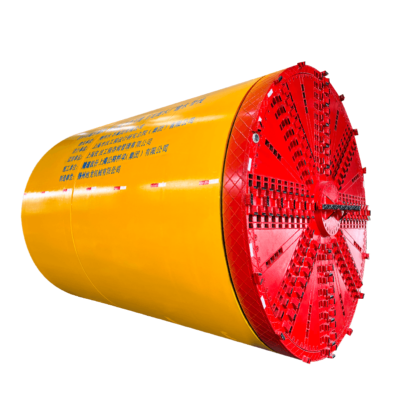
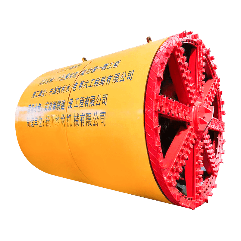
The Cutting Head and Shield
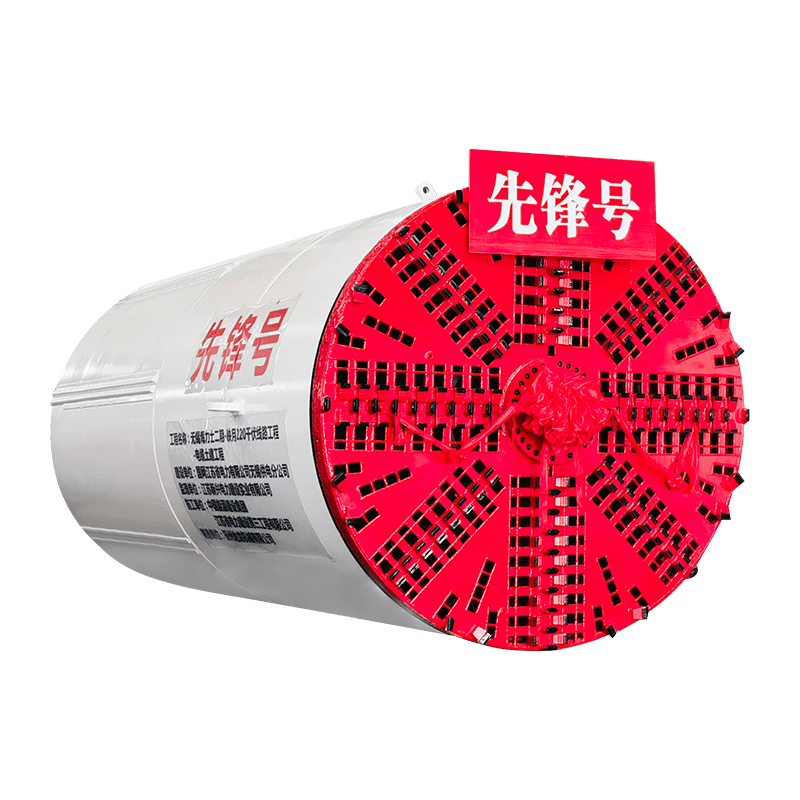
The cutting head is the forward-most element of the pipe jacking machine, designed to excavate the soil and present it for removal through the pipeline bore. Cutting head design varies significantly based on ground conditions. In soft ground — clays, silts, sands, and gravels — a rotary disc or spoke-pattern cutter head with soil-conditioning ports is typically used, often in combination with bentonite or polymer injection to stabilize the face and reduce friction. In mixed ground or rock, more robust cutter heads fitted with disc cutters, drag bits, or tungsten carbide button cutters are required to break the material down for removal. The cutter head is housed within a steel shield that provides ground support at the tunnel face and forms the structural body of the machine.
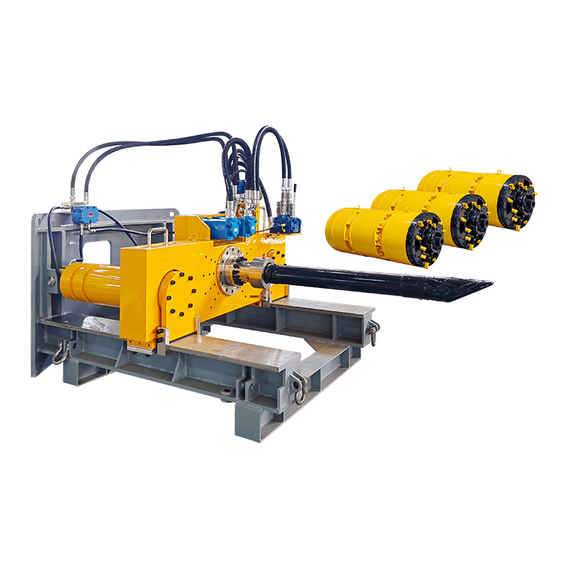
The Jacking Frame and Thrust Cylinders
The main jacking frame is installed in the launch pit behind the pipe string and provides the primary thrust force that advances the machine and pipes through the ground. It consists of a heavy steel reaction frame anchored against the pit rear wall, fitted with hydraulic cylinders — typically two to four large-bore rams — that bear against a thrust ring or thrust collar sitting against the rear face of the last pipe in the string. Jacking forces in pipe jacking operations are substantial: small-diameter microtunneling drives may require 50–200 tonnes of thrust, while large-diameter drives in difficult ground with long pipe strings can demand thrust forces exceeding 1,000 to 3,000 tonnes. The jacking frame must be rated to deliver these forces safely and be correctly sized for the pipe diameter and anticipated ground resistance of the specific drive.
Spoil Removal System
Excavated material must be continuously removed from the tunnel face through the pipeline bore during jacking. The method of spoil removal is one of the key variables that differentiates pipe jacking machine types. Slurry shield machines use a pressurized bentonite slurry circuit to suspend and transport cuttings hydraulically through a slurry pipe to a surface separation plant, where the solids are extracted and the cleaned slurry is recirculated. Earth pressure balance machines mix the excavated soil with conditioning agents to create a plasticized mass that is then extracted by an Archimedean screw conveyor through the pipeline bore to the launch pit. Manual excavation with hand tools and skip removal is still used in larger-diameter drives where worker entry is practical and ground conditions are stable enough to permit it.
Guidance and Steering System
Maintaining line and grade accuracy throughout the drive is critical — pipelines installed off-alignment cause hydraulic gradient problems in gravity sewers, joint stress in pressure mains, and potential clashes with existing services. Pipe jacking machines are steered by adjusting the extension of hydraulic steering cylinders positioned around the shield periphery, which articulate the machine head relative to the following pipe string. Position monitoring is achieved through a laser theodolite mounted in the launch pit that projects a beam onto a target inside the machine — the deviation of the machine from the beam is read by the operator and corrected through the steering cylinders. More sophisticated guidance systems using gyroscopic total stations or ring laser gyroscopes are used on longer drives or curves where a simple laser line is insufficient.
Types of Pipe Jacking Machines and When Each Is Used
Pipe jacking machines are not a single product — they exist in several distinct configurations, each optimized for a different range of bore diameters, ground conditions, and project requirements. Selecting the right machine type is the single most consequential equipment decision on any pipe jacking project.
Microtunneling Machines (MTBM)
Microtunneling machines are remotely operated pipe jacking systems designed for bore diameters typically ranging from 150mm to 1,200mm, though the boundary with larger manned-entry systems is project-specific. The defining characteristic of a microtunneling machine is that the operator does not enter the tunnel during the drive — all steering, monitoring, and machine control is managed from a surface control cabin via an umbilical connection. This remote operation capability makes microtunneling suitable for small-diameter bores where worker entry is physically impossible and for any ground condition where face access presents an unacceptable safety risk. Microtunneling machines are most commonly slurry-type systems, with hydraulic cutting and slurry transport providing continuous face support and efficient spoil removal in soft and mixed ground.
Earth Pressure Balance Pipe Jacking Machines
Earth pressure balance (EPB) pipe jacking machines use the excavated soil itself — conditioned with water, foam, or polymer to achieve a workable plasticity — as the primary face support medium. A pressure bulkhead behind the cutter head maintains a controlled soil pressure against the tunnel face, with the screw conveyor extraction rate balanced against the advance rate to hold the face pressure within a target range. EPB machines are particularly effective in cohesive and mixed soils, waterlogged sands, and urban environments where ground settlement must be minimized. They handle a wide range of diameters from around 600mm up to several meters and are available in both remotely operated and manned-entry configurations depending on bore size.
Slurry Shield Pipe Jacking Machines
Slurry shield machines support the tunnel face using pressurized bentonite slurry and remove cuttings hydraulically through a closed slurry circuit. They excel in saturated granular soils — running sands, gravels, and permeable alluvial deposits — where EPB conditioning is difficult and where maintaining face pressure is critical to preventing blowouts or settlement. The slurry separation plant required at the surface is a significant logistical element on slurry-type projects: it occupies considerable site area, requires careful management of the slurry mix properties, and generates a spoil disposal stream of filter-pressed slurry cake that must be managed as a waste material. Despite this complexity, slurry shield machines are often the only viable technology for water-bearing granular ground at significant depth.
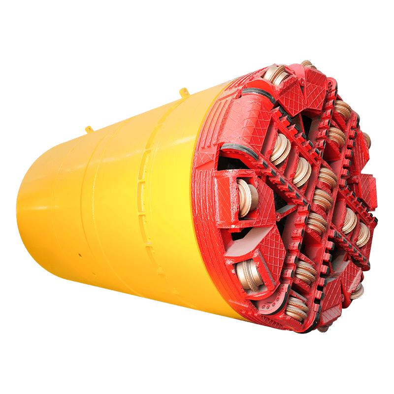
Rock Cutting Pipe Jacking Machines
In rock formations, standard soil cutter heads are ineffective and specialized rock-cutting machines are required. These machines are fitted with full-face disc cutter arrays — similar in principle to a TBM (tunnel boring machine) — that apply high point loads to the rock face to fracture it into chips. The chips are then flushed or conveyed out of the bore. Rock jacking machines must be matched to the compressive strength, abrasivity, and fracture characteristics of the specific rock formation: soft sedimentary rocks such as chalk or mudstone can be handled by reinforced drag bit heads, while hard igneous or metamorphic rocks with UCS values above 100 MPa require full-face disc cutters in harder steel grades. Cutter wear rates in abrasive rock are a major cost driver and must be factored into project budgets from the outset.

Ground Conditions and Their Impact on Machine Selection
No single pipe jacking machine type performs well across all ground conditions. The geotechnical investigation — boreholes, trial pits, laboratory testing of soil samples, and groundwater level monitoring — is the essential foundation on which every machine selection decision must be based. Specifying the wrong machine for the ground conditions encountered is one of the most frequent causes of pipe jacking project failure, leading to stuck machines, blow-outs, excessive settlement, or complete drive abandonment.
The table below summarizes the general relationship between ground conditions and appropriate pipe jacking machine types:
| Ground Condition | Groundwater Present | Recommended Machine Type | Key Consideration |
| Stiff clay / cohesive soil | Low / None | EPB or open face shield | Cutter head clogging in sticky clays |
| Soft clay / silt | Moderate | EPB with conditioning | Settlement risk; face pressure control critical |
| Saturated sand / gravel | High | Slurry shield MTBM | Slurry plant logistics; blowout prevention |
| Mixed ground (soil + boulders) | Variable | Slurry or EPB with rock cutting capability | Boulder obstruction handling; cutter wear |
| Soft rock (chalk, mudstone) | Low to Moderate | Rock cutter head with drag bits | Bit wear rate; lubrication at pipe-ground interface |
| Hard rock (granite, basalt) | Variable | Full-face disc cutter rock machine | High cutter wear cost; high thrust force requirement |
Managing Jacking Forces and Using Intermediate Jacking Stations
As the pipe string lengthens during a drive, the friction acting on the outside surface of the pipes accumulates and the total jacking force required to advance the system increases progressively. On short drives in favorable ground, this buildup is manageable within the capacity of the main jacking frame alone. On longer drives — particularly those exceeding 100–150 meters, or shorter drives in abrasive or high-friction ground — the accumulated skin friction can exceed the thrust capacity of the main frame and the structural load capacity of the pipe joints. This is where intermediate jacking stations become essential.
An intermediate jacking station (IJS) is a short steel cylinder fitted with its own set of hydraulic rams, installed within the pipe string at predetermined intervals during the drive. When the jacking force approaches its limit, the IJS rams are activated to push the forward portion of the pipe string independently while the main jacks reset. By dividing the pipe string into segments and activating IJS units sequentially, the maximum force applied to any individual pipe joint is kept within safe structural limits, and the drive can continue well beyond what the main jacking frame alone could achieve. Well-designed pipe jacking projects on long drives specify IJS positions in advance based on calculated friction loads, with additional positions pre-planned in case ground conditions are worse than anticipated.
Lubrication of the pipe-to-ground interface using bentonite slurry or polymer gel injected through ports in the pipe wall is the other primary strategy for managing jacking forces. An effective lubrication program can reduce pipe-wall skin friction by 50–80% compared to unlubricated drives, dramatically extending the achievable drive length and reducing the number of IJS units required. Lubrication must be maintained continuously throughout the drive — allowing it to break down or be absorbed by the surrounding ground rapidly increases friction and can result in the pipe string becoming stuck.
Pipe Materials Used in Pipe Jacking Operations
The pipe sections pushed through the ground by a pipe jacking machine must withstand both the jacking thrust loads transmitted along their axis and the external ground and groundwater pressures acting on their walls throughout their service life. Not all pipe materials are suitable for jacking, and the choice of pipe type has direct implications for bore diameter, drive length, allowable deflection at joints, and long-term pipeline performance.
- Reinforced concrete jacking pipe: The most widely used material for sewer jacking in medium to large diameters (300mm to 3,000mm and beyond). Concrete jacking pipes are manufactured to specific jacking standards — EN 1916 in Europe, ASTM C76 in North America — with hardened steel end rings at each joint face to distribute jacking loads evenly and minimize joint stress concentration. They offer excellent long-term durability, chemical resistance to sewer gases, and competitive cost at larger diameters.
- Vitrified clay jacking pipe: Used in smaller sewer diameters, typically 150mm to 600mm. Vitrified clay provides exceptional resistance to chemical attack from aggressive sewage and industrial effluents, making it the preferred choice for chemically demanding sewer environments. Its brittleness compared to concrete requires careful handling and limits the jacking forces that can be applied.
- Steel jacking pipe: Used for water and gas transmission mains, oil pipelines, and casing pipes in larger diameters. Steel provides very high compressive and tensile strength, allowing the application of high jacking forces and making it suitable for long drives and hard ground conditions. External corrosion protection — fusion-bonded epoxy, polyurethane coating, or cathodic protection — is essential for long service life.
- GRP (glass fiber reinforced polymer) jacking pipe: Combines high strength with light weight and excellent corrosion resistance. GRP jacking pipes are increasingly specified for chemically aggressive environments and for drives where reduced pipe weight simplifies handling in confined launch pits. They require careful joint design to ensure adequate load transfer under jacking forces.
- Polymer concrete and HOBAS pipe: Centrifugally cast glass fiber reinforced polymer mortar (CCFRPM) pipes combine the chemical resistance of polymer with the compressive strength needed for jacking applications. Widely used in aggressive sewer and industrial drainage applications across Europe and increasingly in other markets.
Key Project Planning Considerations Before Mobilizing a Pipe Jacking Machine
Pipe jacking projects that encounter serious problems in the field are rarely unlucky — they are almost always the result of inadequate planning, insufficient ground investigation, or unrealistic assumptions made during design. The following planning elements deserve careful attention before any pipe jacking machine is mobilized to site.
- Geotechnical investigation scope and quality: Boreholes should be spaced at intervals appropriate to the ground variability of the site — typically no more than 50 meters along the drive alignment for urban projects — and should extend to at least 3 pipe diameters below the invert level of the proposed bore. Laboratory testing should include particle size distribution, plasticity index, undrained shear strength, unconfined compressive strength for rock, and groundwater chemistry where corrosion of pipes or machine components is a concern.
- Existing services survey: A full utility survey using ground-penetrating radar, electromagnetic location, and a review of all available utility records must be completed before drive alignment is finalized. An undetected utility crossing an active bore has the potential for catastrophic consequences — service strikes on gas mains, high-voltage cables, or water mains in the vicinity of a live drive are among the most serious risks in urban trenchless construction.
- Launch and reception pit design: The launch pit must be large enough to accommodate the jacking frame, pipe handling equipment, spoil removal system, and provide safe working access for the crew. Minimum pit dimensions are determined by the pipe diameter, machine length, and jacking stroke. The pit must be adequately shored and dewatered, and the rear thrust wall must be structurally capable of resisting the maximum anticipated jacking force without movement or failure.
- Drive length and curvature: Each machine type and pipe material combination has a maximum achievable drive length, beyond which jacking forces or pipe joint stresses become unmanageable. Similarly, curved alignments are possible but introduce additional complexity in guidance and increase pipe joint bending loads. Drives exceeding approximately 150 meters or incorporating horizontal or vertical curves should be assessed by a specialist trenchless engineer before machine selection is finalized.
- Settlement monitoring and risk assessment: For drives beneath sensitive structures — railway tracks, historic buildings, bridge abutments, or operational industrial facilities — a settlement monitoring program using surface survey monuments, precise leveling, and tiltmeters on sensitive structures should be established before the drive begins. Trigger and action levels for machine parameter adjustment or drive suspension should be agreed with affected infrastructure owners in advance.
Common Problems During Pipe Jacking and How Experienced Contractors Handle Them
Even well-planned pipe jacking drives encounter problems. Ground conditions rarely match borehole data exactly, machine components wear or malfunction, and unexpected obstructions are a reality of urban subsurface construction. The difference between a project that recovers from these events and one that results in a stuck machine or aborted drive usually comes down to the experience of the crew and the contingency measures built into the project plan.
Obstructions at the Tunnel Face
Boulders, cobbles, old masonry foundations, timber piles, and decommissioned utilities are among the most common unexpected obstructions encountered during pipe jacking drives in urban areas. In manned-entry diameter drives, workers can sometimes break obstructions down with hand tools or pneumatic breakers under the protection of the shield. In smaller microtunneling diameters where entry is not possible, contingency options include interventional access from a breakout excavation above the drive, surface-drilled jet grouting or resin injection to stabilize the ground around the obstruction, or in extreme cases, abandoning the drive and recovering the machine from a new pit ahead of the blockage.
Excessive Jacking Force Buildup
When jacking forces rise faster than anticipated, the first response should always be to assess and optimize the lubrication program — increasing injection volume and frequency, checking that lubrication ports are not blocked, and verifying that the annular void around the pipes is adequately filled. If lubrication optimization does not arrest the force increase, activating intermediate jacking stations earlier than planned is the next step. Forcing a stuck drive by applying maximum thrust is rarely productive and risks pipe joint damage, machine component failure, or surface uplift. Pausing the drive and allowing the ground to relax slightly around the pipe string — combined with intensified lubrication — often achieves more progress than continued forcing.
Off-Line Deviation
Guidance deviations that are caught early are manageable — the steering cylinders can progressively correct the machine heading over the next several pipe lengths without creating unacceptable joint angles. Deviations that go undetected until they are large are much more difficult to recover from and may result in pipe joint stress, surface settlement in an unintended location, or potential conflict with existing services. The best defense against deviation problems is a rigorous monitoring regime — reading and recording the guidance target position after every pipe installation, not just at the start of each shift — and a clear action protocol for what steering corrections are applied at what deviation magnitude.


