


 English
  русский
  عربى
عربى Content
- 1 The Basic Idea Behind a Tunnel Boring Machine
- 2 How a Tunnel Boring Machine Excavates and Advances
- 3 The Main Types of Tunnel Boring Machines
- 4 TBM Cutterhead Design and Cutting Tools
- 5 Tunnel Lining Systems Used with TBMs
- 6 TBM Performance Metrics That Project Teams Track
- 7 Ground Investigations That Inform TBM Selection and Design
- 8 Major Risks on TBM Projects and How They Are Managed
- 9 How TBM Technology Has Evolved and Where It Is Heading
The Basic Idea Behind a Tunnel Boring Machine
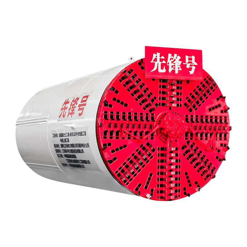
A tunnel boring machine — commonly called a TBM — is a large piece of excavation equipment that bores a circular tunnel through the ground in a single continuous operation, cutting rock or soil at the face while simultaneously installing a structural lining behind it. The concept is straightforward even if the engineering is not: a rotating cutterhead at the front of the machine excavates the material, the excavated spoil is removed through the machine body, and the tunnel is supported by precast concrete or steel segments that are erected inside the machine's trailing shield as it advances. What emerges at the other end of the drive is a finished, lined tunnel ready for fitout.
TBMs are used to build metro lines, railway tunnels, road tunnels, water supply tunnels, sewage tunnels, hydropower headrace tunnels, and utility corridors. They have been used in some of the most challenging and iconic tunnel projects in the world — the Channel Tunnel beneath the English Channel, the Gotthard Base Tunnel through the Swiss Alps, the Thames Tideway Tunnel in London, and dozens of urban metro systems in cities from Tokyo to Istanbul to Sydney. The appeal of the TBM over conventional drill-and-blast or roadheader excavation is its combination of speed, safety, accuracy, and the ability to excavate and line a tunnel simultaneously without exposing the surrounding ground to uncontrolled collapse.
Modern tunnel boring machines are among the most complex and expensive pieces of construction equipment in existence. The largest TBMs exceed 17 meters in diameter and cost upward of $80 million USD. Even modest metro-scale machines in the 6–9 meter diameter range represent investments of $15–40 million and require teams of dozens of engineers, operators, and maintenance technicians to run continuously around the clock. Understanding how these machines work, why there are so many different types, and what drives performance and cost on TBM projects is essential knowledge for anyone involved in major underground infrastructure.
How a Tunnel Boring Machine Excavates and Advances
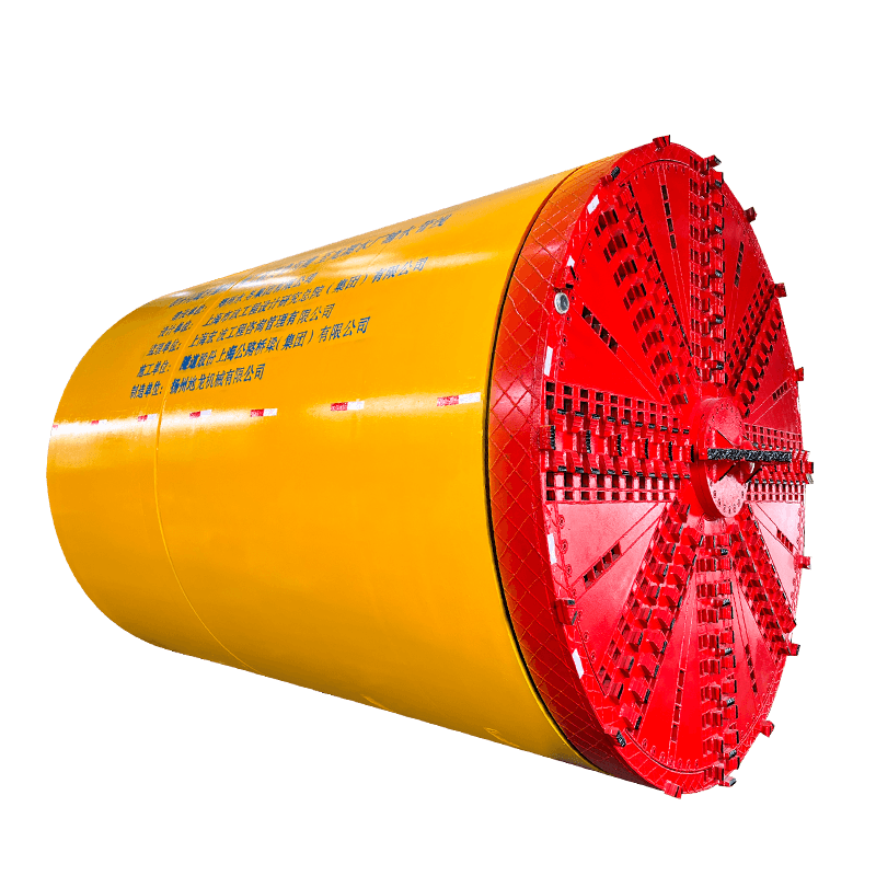
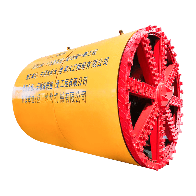
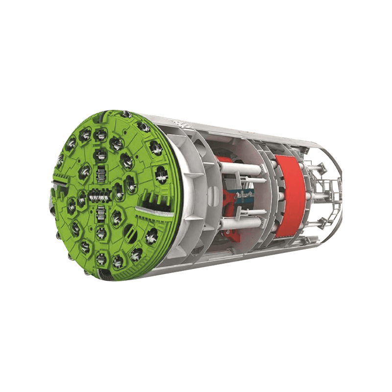
The operational cycle of a TBM is repetitive but precisely choreographed. At the front of the machine, a large circular cutterhead — fitted with cutting tools appropriate to the ground being excavated — rotates against the tunnel face. The cutterhead is driven by a series of electric motors through gearboxes or by direct hydraulic drive, generating both the rotational torque needed to cut the material and the thrust force needed to press the cutting tools into the face. Thrust is provided by hydraulic cylinders that push against the last completed ring of tunnel lining segments installed behind the machine.
As the cutterhead rotates and advances, cuttings fall through openings in the cutterhead face — called muck openings or buckets — into a collection chamber behind the cutterhead. From there, the spoil is conveyed through the machine body by a series of belt conveyors, screw conveyors, or slurry pipelines, depending on the machine type, and transported to the tunnel portal or a shaft for removal from the site. Simultaneously, in the annular space just behind the cutterhead, a segment erector — a robotic arm working inside the tail shield — picks up precast concrete lining segments delivered from the surface and builds them into a complete ring. Once a full ring is erected, the thrust cylinders advance to push against the new ring, and the cycle begins again.
In favorable ground conditions, a well-operated TBM can complete multiple rings per shift, with each ring representing an advance of typically 1.2 to 2.0 meters of tunnel. Daily advance rates on metro-scale TBM drives range from 8 to 20 meters per day under normal conditions, with exceptional ground and machine performance occasionally achieving 30 meters or more in a 24-hour period. Over a full drive lasting many months, these rates accumulate into kilometers of completed tunnel — a productivity that no conventional excavation method can match at equivalent scale.
The Main Types of Tunnel Boring Machines
There is no single universal TBM design. The machine must be selected and configured for the specific ground conditions along the tunnel alignment, and the consequences of choosing the wrong machine type range from poor performance and excessive cutter wear to catastrophic ground collapse or flooding. The primary classification of TBM types follows the face support method — how the machine manages the stability of the tunnel face during excavation.
Open-Face Hard Rock TBMs
In competent, self-supporting rock — where the ground is strong enough to stand unsupported at the tunnel face for the duration of the excavation cycle — an open-face hard rock TBM is the standard choice. These machines, also called gripper TBMs or main beam TBMs, use large hydraulic grippers that extend laterally from the machine body and press against the tunnel walls to provide the reaction force for the thrust cylinders. The cutterhead is fitted with disc cutters — hardened steel wheels that roll across the rock face under high point loads, fracturing the rock along cracks that propagate between adjacent cutter tracks and breaking it into chips. Open-face hard rock TBMs can achieve very high penetration rates in strong, competent rock and have been responsible for some of the fastest tunneling records ever recorded.
The limitation of open-face gripper TBMs is their inability to cope with weak or squeezing ground, fractured rock zones, water inflows, or any condition where the tunnel walls cannot provide reliable gripper reaction. In mixed ground or variable rock quality — common on long alpine tunnels — the machine must be capable of installing temporary ground support measures including rock bolts, mesh, and shotcrete in the annular space around the bore while continuing to advance, which slows production significantly.
Earth Pressure Balance TBMs
Earth pressure balance TBMs (EPB TBMs) are the dominant machine type for soft ground tunneling in urban environments. The defining feature of an EPB TBM is a pressure bulkhead immediately behind the cutterhead that creates a sealed excavation chamber. Excavated soil fills this chamber, and conditioning agents — water, foam, polymer, or bentonite — are injected through ports in the cutterhead to convert the soil into a plasticized, semi-fluid mass with the right consistency to transmit pressure. The pressure in the excavation chamber is actively controlled to match the combined earth and groundwater pressure at the tunnel face, preventing inflow of soil or water and minimizing surface settlement.
Spoil is extracted from the pressurized excavation chamber by an Archimedean screw conveyor — a rotating helix inside a sealed tube — that acts as a pressure lock, allowing material to be discharged at atmospheric pressure on the atmospheric side of the machine while maintaining the required face pressure in the chamber. EPB TBMs are effective across a wide range of soft ground types including clays, silts, sands, and gravels, and they are the most commonly specified machine for metro and urban railway tunnels worldwide. Their ability to control ground movement makes them indispensable in dense urban environments where settlement above the tunnel must be kept within millimeters to protect buildings and infrastructure.
Slurry Shield TBMs
Slurry shield TBMs support the tunnel face using pressurized bentonite slurry rather than the excavated soil itself. The excavation chamber behind the cutterhead is filled with slurry under pressure, and the slurry simultaneously stabilizes the face and transports cuttings in suspension back through a slurry pipeline to a surface separation plant. At the separation plant, the cuttings are extracted using screens, hydrocyclones, and centrifuges, and the cleaned slurry is reconditioned and pumped back to the tunnel face in a closed circuit. Slurry shield TBMs excel in saturated granular ground — running sands, gravels, and mixed soils below the water table — where EPB face pressure control is difficult and where the risk of blowout or uncontrolled inflow is highest. They are also the preferred machine type when tunneling beneath rivers, harbors, or other water bodies where the consequences of face instability are severe.
The primary disadvantage of slurry TBMs compared to EPB machines is the complexity and space requirement of the slurry circuit and separation plant. The surface plant occupies significant area, the slurry requires continuous management and property adjustment, and the filter-pressed slurry cake produced as a waste product must be disposed of as a managed material. On constrained urban sites where surface space is limited, this additional logistical demand can be a significant factor in machine selection.
Mixed Shield and Convertible TBMs
Long tunnel alignments frequently pass through several different ground types — rock at depth, transitioning to mixed ground, then soft urban soils closer to the portal. To handle these transitions without retrieving and replacing the machine, manufacturers offer mixed shield TBMs and convertible TBMs that can operate in both EPB and slurry modes, or that incorporate elements of both hard rock and soft ground design. Convertible machines are more expensive to procure and more complex to operate and maintain, but on projects where ground variability is high and the cost of machine retrieval would be prohibitive, they are the only practical option.
TBM Cutterhead Design and Cutting Tools
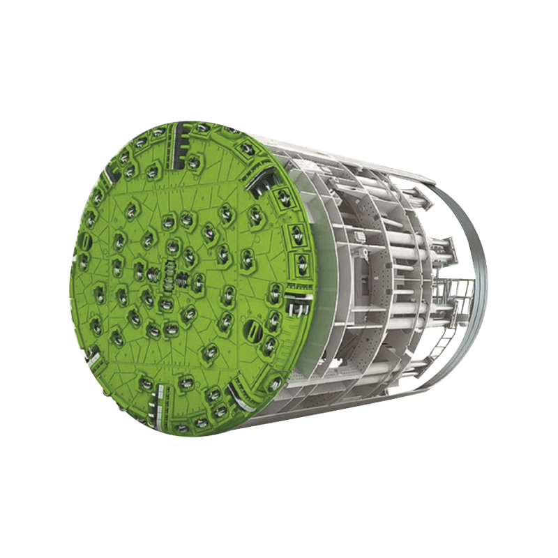
The cutterhead is the most critical and wear-intensive component of any tunnel boring machine. Its design — diameter, spoke configuration, opening ratio, cutter tool type and layout — determines how effectively the machine excavates the ground, how quickly tools wear, and how frequently interventions are required to replace worn cutters. Getting cutterhead design right for the specific geology of a project has a direct and measurable impact on the project's advance rate, tool cost, and overall schedule.
Disc Cutters for Rock
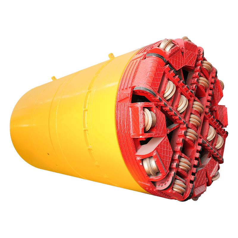
In hard rock, the primary cutting tool is the disc cutter — a hardened steel ring mounted on a bearing assembly that rolls across the rock face under high point loads applied by the TBM's thrust force. As the cutterhead rotates, each disc cutter scribes a circular groove in the rock face. The stress field between adjacent groove tracks causes the rock to fracture and spall into chips — a process called chipping or cratering — which are swept into the muck openings by cutterhead buckets. Disc cutter diameter has increased over decades of development; modern cutters are typically 432mm (17 inches) or 483mm (19 inches) in diameter, capable of sustaining individual loads of 250–320 kN. Cutter wear rate depends on rock abrasivity — quantified by the Cerchar Abrasivity Index — and is one of the dominant cost drivers on hard rock TBM projects, with cutter replacement in highly abrasive rock sometimes requiring interventions every 50–100 meters of advance.
Soft Ground Cutting Tools
In soft ground, disc cutters are replaced or supplemented by drag bits, scraper tools, and rippers that shear and scrape the soil rather than fracturing it by point loading. Cutterhead design for soft ground prioritizes mixing and conditioning of the excavated material as much as cutting — spoke-pattern heads with large muck openings allow soil to flow freely into the excavation chamber, while injection ports distributed across the face deliver conditioning agents directly to the point of cutting. In mixed ground where cobbles, boulders, or rock bands may be encountered alongside soft soil, the cutterhead must carry both drag bits for the soil and disc cutters for the hard material, a combination that requires careful tool spacing and layout to function effectively across the full range of ground types.
Tunnel Lining Systems Used with TBMs
The tunnel lining installed behind a TBM serves multiple functions simultaneously: it provides immediate structural support to prevent ground movement, it forms the permanent structural envelope of the tunnel that must carry ground loads, water pressure, and service loads throughout the design life of the infrastructure, and in pressurized-face TBMs it provides the reaction surface against which the thrust cylinders push to advance the machine. The design and quality of the lining system is therefore inseparable from the performance of the TBM operation itself.
The dominant lining system for shield TBMs in soft ground is the precast concrete segmental lining. Each ring of lining is assembled from a set of curved precast concrete segments — typically five to eight segments plus a smaller closing key segment — that are bolted or connected together and to adjacent rings to form a continuous cylindrical shell. Segment dimensions are precisely controlled: diameter tolerances of ±1mm and thickness variations of ±2mm are typical quality requirements, because the segments must fit together perfectly under the complex three-dimensional geometry of the erected ring. Grouting of the annular void between the outer face of the segments and the excavated ground profile is performed through grout ports in the segment tails immediately behind the TBM tail shield, using two-component grout that sets rapidly to prevent ground movement into the void before the primary grout cures.
For hard rock TBMs in competent ground, an unlined or partially lined tunnel is sometimes acceptable for water tunnels and other non-public infrastructure, with the rock itself providing the primary structural support. More commonly, a cast-in-place concrete lining or a simplified precast segmental lining is installed as a second-pass operation after the TBM has passed, reducing the immediate schedule pressure of simultaneous lining erection during the drive.

TBM Performance Metrics That Project Teams Track
TBM project performance is monitored through a set of operational metrics that reveal how efficiently the machine is cutting, how much time is being lost to non-productive activities, and whether the machine and ground conditions are within expected parameters. These metrics are recorded continuously by the machine's data acquisition system and reviewed by the project team on a shift-by-shift basis.
| Metric | Definition | Why It Matters |
| Penetration Rate (PR) | Advance per cutterhead revolution (mm/rev) | Indicates cutting efficiency and tool condition |
| Advance Rate (AR) | Distance tunneled per unit time (m/day or m/week) | Primary schedule performance indicator |
| Utilization Rate | % of total time the TBM is actively boring | Reveals downtime losses from maintenance, interventions, logistics |
| Specific Energy | Energy consumed per unit volume of rock excavated (kWh/m³) | Efficiency indicator; rises sharply with worn cutters |
| Face Pressure | Pressure maintained in excavation chamber (bar) | Critical for face stability and settlement control in soft ground |
| Cutter Wear Rate | Number of cutter changes per km of advance | Direct driver of tool cost and intervention downtime |
| Grout Injection Volume | Volume of tail void grout injected per ring | Confirms annular void is being filled; under-grouting causes settlement |
Utilization rate deserves particular attention because it is the metric over which the project team has the most direct control. A TBM with a penetration rate of 6mm/rev operating at 40% utilization will advance more slowly than a machine with a penetration rate of 4mm/rev operating at 70% utilization. The non-boring time that reduces utilization is consumed by segment erection, cutter inspections and changes, tail seal maintenance, probe drilling ahead of the face, mucking logistics delays, and planned and unplanned maintenance. Systematic analysis of where downtime is occurring — and targeted action to reduce the largest contributors — is one of the highest-leverage activities available to a TBM project management team.
Ground Investigations That Inform TBM Selection and Design
A TBM project's success is largely determined before the machine ever enters the ground — by the quality and thoroughness of the geotechnical investigation program that characterizes the ground conditions along the alignment. TBMs are bespoke pieces of equipment manufactured to specific geological parameters; once built and launched, they cannot be fundamentally redesigned if the ground proves different from what was assumed. The consequences of inadequate ground investigation on a TBM project — stuck machines, unexpected water inflows, severe cutter wear, surface settlements, or complete drive abandonment — are measured in tens or hundreds of millions of dollars of additional cost and years of schedule delay.
- Borehole spacing and depth: Investigation boreholes along a TBM alignment should typically be spaced at 50–100 meter intervals, with closer spacing at critical locations such as launch and reception shaft positions, river crossings, and areas of known geological complexity. Boreholes must extend to at least three tunnel diameters below the tunnel invert to characterize the full zone of influence of the excavation.
- Rock strength and abrasivity testing: For hard rock TBM projects, laboratory testing should include uniaxial compressive strength (UCS), Brazilian tensile strength, point load index, Cerchar Abrasivity Index (CAI), and petrographic thin section analysis of representative core samples from each lithological unit along the alignment. These parameters directly inform disc cutter specification, cutterhead thrust requirements, and cutter replacement cost predictions.
- Groundwater characterization: Piezometric monitoring boreholes installed along the alignment — with readings taken over a full seasonal cycle where time permits — establish the groundwater regime that the TBM must operate within. Artesian conditions, perched water tables, and high-permeability zones that could sustain large inflows into the tunnel must be identified and planned for during machine design and grouting strategy development.
- Soil classification and particle size distribution: For soft ground TBM projects, detailed particle size analysis of soil samples from across the alignment is essential for EPB conditioning design and slurry circuit specification. The presence of gravel or cobble fractions above certain percentages can make EPB operation problematic and may indicate slurry shield as the more appropriate machine type.
- Obstruction and contamination surveys: In urban alignments, a comprehensive search for existing underground obstructions — decommissioned piles, old masonry structures, buried infrastructure, contaminated ground — must be completed before machine procurement to allow the cutterhead to be designed with appropriate boulder-breaking or obstruction-handling capability.
Major Risks on TBM Projects and How They Are Managed
TBM tunneling is among the most technically complex and risk-intensive activities in the construction industry. The combination of large capital expenditure, underground working conditions, geological uncertainty, and the physical impossibility of changing fundamental equipment decisions once a drive has begun creates a risk environment that demands structured risk management from the earliest stages of project development.
Face Instability and Settlement
In soft ground tunneling, loss of face pressure control is one of the most serious risks. If the pressure in the excavation chamber of an EPB or slurry TBM drops below the combined earth and groundwater pressure at the face — even momentarily — the ground can flow into the machine, causing a sinkhole or settlement trough at the surface above. In urban environments where the tunnel passes beneath occupied buildings, live railway lines, or busy road intersections, even a modest settlement event of 20–30mm can cause structural damage and disruption costing many times the tunneling contract value. Face pressure monitoring and control is therefore continuous and critical, with automatic alarms and operator intervention protocols for any deviation beyond established limits. A surface settlement monitoring array — typically optical survey prisms, precise leveling benchmarks, and automated tiltmeters on sensitive structures — provides independent confirmation that the TBM's face pressure management is achieving the required settlement performance.
Stuck TBM
A TBM that becomes immovably stuck in the ground — due to ground squeezing around the shield, loss of lubrication, cutter blockage, or encountering a major obstruction — is one of the most expensive scenarios in underground construction. Recovery operations can involve de-pressurizing the tunnel, constructing a rescue shaft directly above the machine, excavating around the shield to relieve the ground pressure, and potentially dismantling and reassembling major machine components underground. Such operations have taken months and cost tens of millions of dollars on high-profile projects. Prevention is clearly preferable: continuous monitoring of shield friction forces, proactive lubrication management, face mapping ahead of the machine using probe drilling, and having a rehearsed stuck machine contingency plan agreed with the client and insurer before the drive begins are all standard risk management measures on well-run TBM projects.
Unexpected Water Inflows
Major water inflows — from faults, karstic voids, permeable gravel lenses, or unexpectedly high piezometric heads — can overwhelm the drainage capacity of the TBM and its backup systems, flood the tunnel, and in the worst cases endanger workers. Systematic probe drilling ahead of the TBM face — typically to a distance of 30–50 meters ahead using percussive or rotary drill rigs mounted on the cutterhead or within the machine — provides early warning of water-bearing features. Pre-excavation grouting from within the tunnel, or from the surface above the alignment, can seal permeable zones before they are intersected by the cutterhead. For tunnels in particularly water-sensitive ground, the TBM may be specified with hyperbaric intervention capability — the ability to pressurize the work chamber to balance groundwater pressure, allowing workers in compressed air to enter the excavation chamber for cutter changes and face inspection.
How TBM Technology Has Evolved and Where It Is Heading
The tunnel boring machine has undergone continuous development since the first successful modern TBM — developed by James Robbins for the Oahe Dam tunnel project in South Dakota in the early 1950s. Each decade has brought advances in cutterhead design, cutterhead drive systems, segment erection technology, guidance precision, and machine reliability that have progressively expanded the range of ground conditions and project scales where TBMs are the preferred excavation method.
Current development focus areas in TBM technology include real-time ground characterization using sensors embedded in the cutterhead — measuring vibration, torque distribution, and acoustic signatures to identify changes in rock type or soil composition before they cause operational problems. Machine learning algorithms are being applied to the large datasets generated by modern TBM control systems to predict cutter wear rates, optimize penetration rate against face pressure, and schedule maintenance interventions before failures occur rather than in response to them. Automation of segment handling and erection — one of the most time-consuming and physically demanding elements of the tunneling cycle — is advancing rapidly, with fully automated erectors on some modern machines capable of positioning and bolting segments with minimal human involvement.
At the frontier of TBM development, researchers and machine manufacturers are exploring multi-mode machines capable of boring simultaneously in rock and soft ground without reconfiguration, and investigating novel cutting technologies — laser-assisted rock fracturing, high-pressure water jet cutting — that could eventually supplement or replace conventional mechanical disc cutters in specific rock types. The fundamental challenge remains the same as it has always been: maximizing the proportion of time the machine spends cutting and minimizing everything else. In that pursuit, the tunnel boring machine continues to evolve as one of the most consequential pieces of engineering machinery ever built.


