


 English
  русский
  عربى
عربى Content
- 1 What a Rock Pipe Jacking Machine Is and Why Rock Conditions Demand Specialist Equipment
- 2 How Rock Pipe Jacking Machines Work: The Complete Process
- 3 Cutterhead Types for Different Rock Conditions
- 4 Jacking Force Calculations and Intermediate Jacking Stations
- 5 Lubrication and Annular Grouting in Rock Pipe Jacking
- 6 Ground Investigation Requirements for Rock Pipe Jacking Projects
- 7 Key Specifications to Compare When Selecting a Rock Pipe Jacking Machine
- 8 Common Problems in Rock Pipe Jacking Drives and How to Prevent Them
- 9 Selecting the Right Rock Pipe Jacking Machine for Your Project
What a Rock Pipe Jacking Machine Is and Why Rock Conditions Demand Specialist Equipment
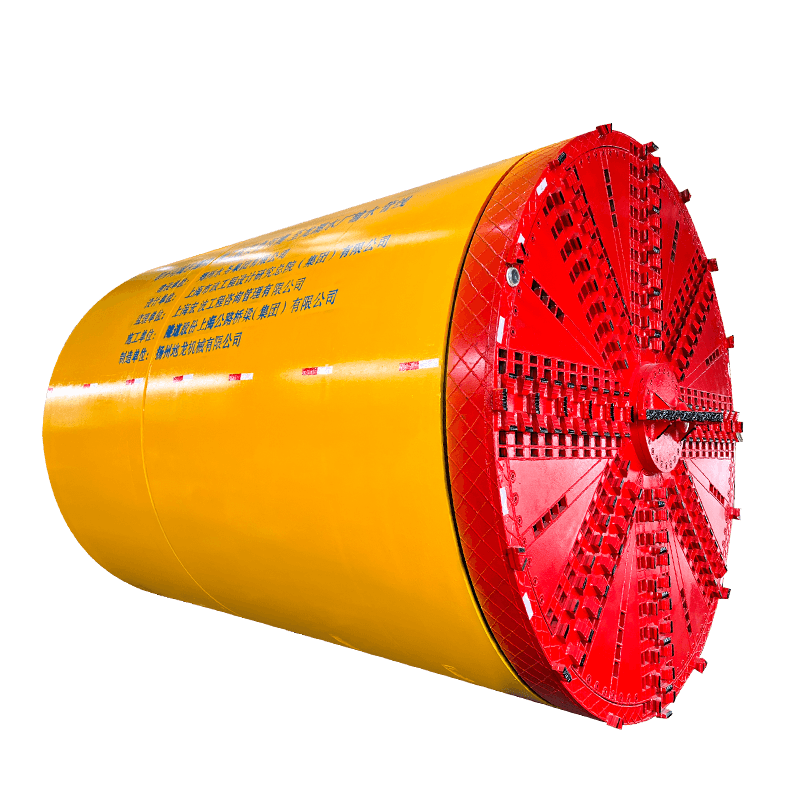
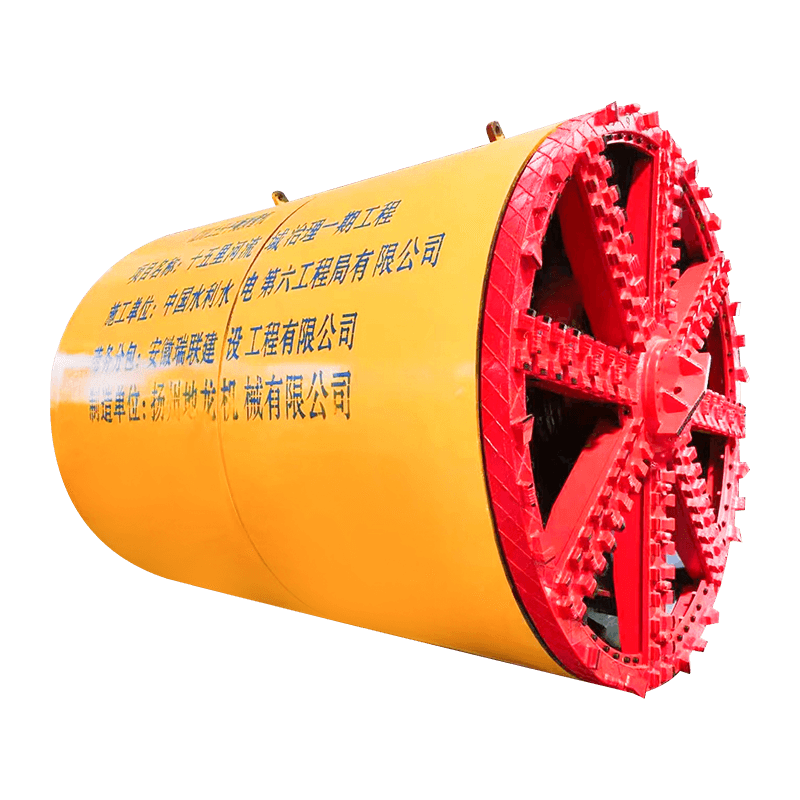
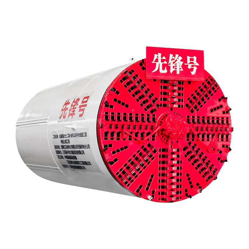
A rock pipe jacking machine is a specialist piece of trenchless construction equipment designed to bore through hard or mixed rock formations while simultaneously installing a string of pipes behind it, using hydraulic jacking forces applied from a launch shaft to push the entire pipe string and machine forward through the ground. The machine excavates the rock face at the bore front, removes the spoil through the installed pipe string, and maintains the precise line and grade required for the finished pipeline — all without open excavation at the surface. Rock pipe jacking machines are the equipment of choice for installing gravity sewers, water mains, gas pipelines, and cable ducts beneath roads, railways, rivers, and urban infrastructure where surface disruption is prohibited or impractical and where the ground conditions include rock too hard or abrasive for standard soft-ground pipe jacking equipment to handle.
The distinction between a standard pipe jacking machine and one designed specifically for rock conditions is fundamental. Soft-ground microtunnelling machines use slurry pressure or earth pressure balance to support the tunnel face and employ disc cutters or drag picks appropriate for soil and weak rock. In competent hard rock — granite, basalt, quartzite, sandstone, or limestone with unconfined compressive strength (UCS) above 80 to 100 MPa — these cutting tools wear rapidly, the excavation rate drops to unacceptable levels, and the machine may become stuck if the ground self-supports without the fluid pressure the machine relies on. A rock pipe jacking machine addresses all of these challenges with purpose-designed cutterheads carrying disc cutters or button bits rated for hard rock, robust main bearings and drive systems capable of sustaining the high thrust and torque loads that rock excavation demands, and often an open-face or atmospheric working mode appropriate to self-supporting rock conditions.
How Rock Pipe Jacking Machines Work: The Complete Process
The pipe jacking process in rock follows the same fundamental sequence as in softer ground, but each stage involves equipment and procedures adapted to the challenges of hard rock excavation. Understanding the full process clarifies what the machine must do and why its various systems are designed the way they are.
Launch shaft preparation and machine setup
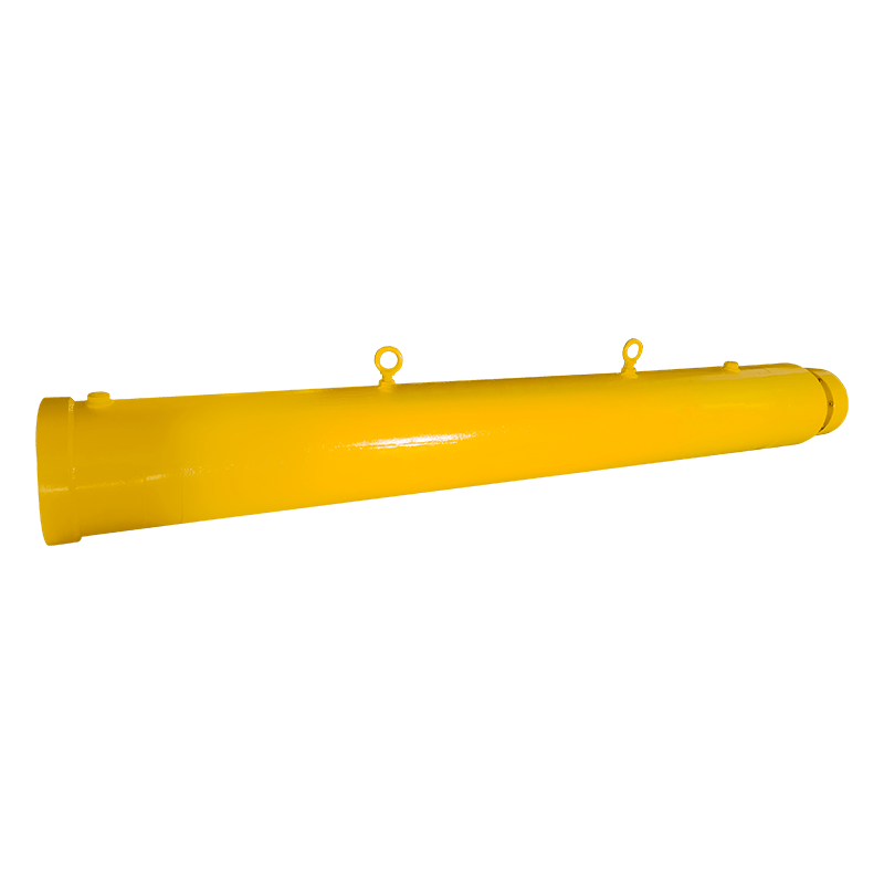
The process begins with the construction of a launch shaft — a vertical excavation from which the machine is lowered and the pipe string is advanced. In rock formations, launch shafts are often formed by drilling and blasting or by rock saw cutting, and must be of sufficient size to accommodate the jacking frame, thrust wall, and the first pipe sections being installed. The thrust wall — a reinforced concrete or steel structure bearing against the rear wall of the shaft — must be designed to resist the full jacking force that will be applied during the drive, which in hard rock conditions can reach several hundred tonnes for even moderate-diameter bores. The machine is lowered into the shaft, set on the jacking frame at the correct line and grade, and connected to the trailing systems — slurry lines, power supply, data cables, and spoil removal conveyor or slurry pipe — before boring commences.
Rock excavation at the cutterhead
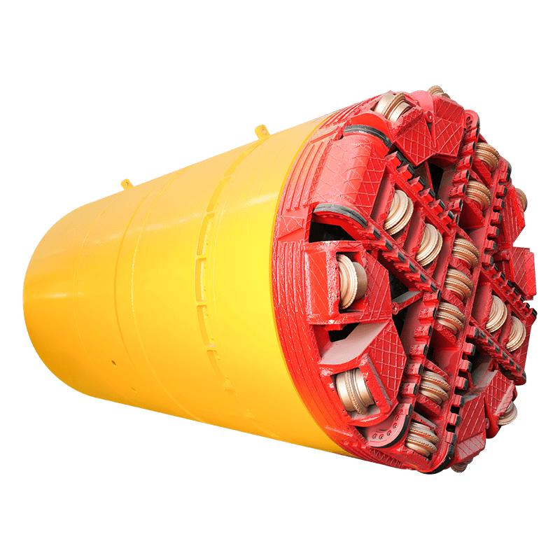
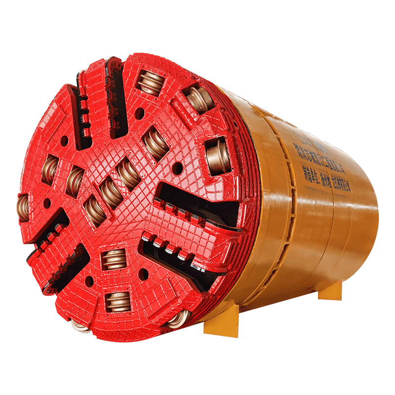
The cutterhead rotates against the rock face under the combined effect of thrust force applied by the jacking system and torque from the cutterhead drive motors. In hard rock, the primary cutting action is performed by disc cutters — hardened steel wheels that roll across the rock face under high point loads, inducing tensile fractures that chip the rock between adjacent cutter paths. The spacing, diameter, and tip load of the disc cutters are engineered for the specific rock type and UCS — harder, more abrasive rocks require closer-spaced, larger-diameter cutters with higher-grade carbide inserts to achieve acceptable penetration rates and cutter life. Softer or fractured rock may be cut more efficiently with drag picks or combination cutterheads that carry both disc cutters and picks for mixed-face conditions.
Spoil removal from the bore
Rock cuttings generated at the cutterhead must be transported back through the installed pipe string to the launch shaft for removal. In slurry-mode rock pipe jacking machines, water or bentonite slurry is pumped to the cutterhead, where it mixes with the rock chips and is pumped back as a slurry to a separation plant at the surface. This method handles fine rock particles and small chips efficiently but requires sufficient slurry velocity to transport the coarser rock fragments produced in hard rock — a consideration that affects slurry pump sizing and pipeline diameter. In some rock pipe jacking configurations, particularly in self-supporting competent rock, mechanical conveying — a screw conveyor or drag conveyor running through the pipe string — is used instead of slurry transport, eliminating the need for a separation plant and simplifying site operations.
Pipe installation and jacking sequence
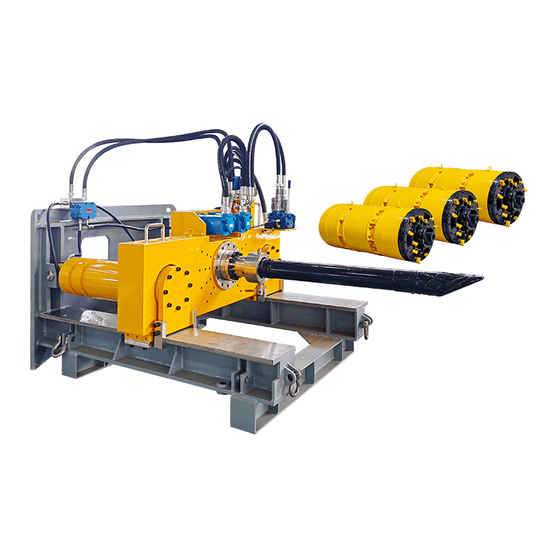
As the machine advances, pipe sections are lowered into the launch shaft and added to the rear of the pipe string, which is pushed forward by the main jacking frame. Each jacking stroke advances the string by one pipe length — typically 1.0 to 3.0 metres depending on pipe diameter and shaft depth. The jacking frame then retracts, a new pipe is lowered and positioned, and the next stroke begins. Intermediate jacking stations — hydraulic jacks installed between pipe sections at intervals along the drive — are used on longer drives to reduce the cumulative friction load that would otherwise require the main jacking frame to push the entire pipe string length, which in rock drives can reach several thousand tonnes on long bores.
Steering and grade control
Maintaining the specified line and grade through rock requires a steering system capable of overcoming the directional tendencies that rock anisotropy and fracture patterns can impose on the machine. Rock pipe jacking machines use articulated shields with hydraulic steering cylinders that deflect the front section of the machine relative to the trailing pipe, allowing corrections to be made continuously during the drive. A laser theodolite or gyroscopic guidance system monitors the machine position relative to the design alignment, with real-time data displayed at the surface control station. In hard rock, steering corrections must be applied gradually — abrupt steering adjustments in stiff ground can cause pipe joint damage or increased friction loads — and the steering geometry of the machine must be matched to the pipe diameter and joint tolerance to avoid over-stressing the pipe string during direction changes.
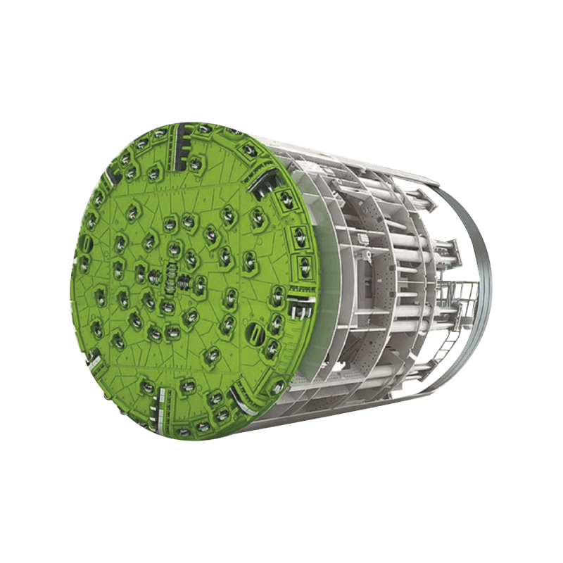
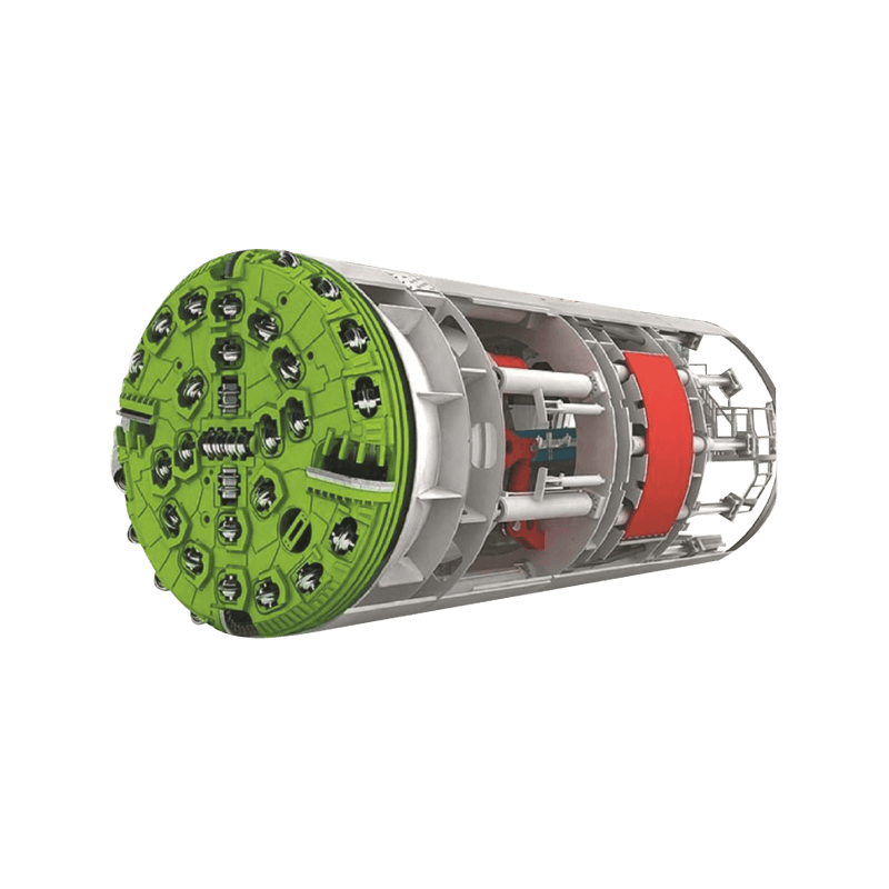
Cutterhead Types for Different Rock Conditions
The cutterhead is the defining component of a rock pipe jacking machine — its design determines whether the machine can excavate the target rock effectively, how quickly cutter wear occurs, and how the machine performs in mixed face conditions. Selecting or specifying the correct cutterhead configuration for the ground conditions is one of the most critical decisions in project planning.
| Cutterhead type | Rock UCS range | Primary cutting tools | Best suited conditions | Key limitation |
| Disc cutter head (full face) | 80 – 300+ MPa | 17" or 19" disc cutters | Competent hard rock, granite, basalt | Poor performance in soft or fractured zones |
| Button bit / roller bit head | 40 – 150 MPa | Tungsten carbide button bits | Medium-hard rock, limestone, sandstone | High wear in very hard or abrasive rock |
| Combination head (disc + pick) | 20 – 120 MPa | Disc cutters + drag picks | Mixed face: rock and soil, variable hardness | Compromise performance in pure hard rock |
| Raise bore head (adapted) | 100 – 250 MPa | Tricone roller bits | Very hard competent rock, small diameters | Limited diameter range; high torque demand |
Cutter inspection and replacement access is a critical design consideration for rock pipe jacking machines. In larger-diameter machines (typically DN 1200 and above), it is possible for personnel to enter the cutterhead chamber under safe atmospheric conditions in self-supporting rock to inspect and replace worn cutters during the drive. In smaller-diameter machines, cutter replacement requires either retracting the machine to the launch shaft — a significant time and cost penalty — or using remotely operated cutter exchange systems that allow worn tools to be replaced without man-entry. The feasibility and cost of cutter changes should be factored into drive planning, particularly for long drives in highly abrasive rock where cutter consumption rates are high.
Jacking Force Calculations and Intermediate Jacking Stations
The total jacking force required to advance a rock pipe jacking machine is one of the most important parameters in project planning — it determines the capacity of the main jacking frame, the structural design of the thrust wall, the required strength of the pipe sections, and whether intermediate jacking stations are needed. Underestimating jacking force leads to drives that stall, pipes that are damaged in over-thrust, or projects that cannot be completed.
The total jacking force is the sum of the face resistance — the force required to advance the cutterhead through the rock — and the skin friction along the full length of the installed pipe string. Face resistance in rock is primarily a function of the rock UCS, the cutterhead area, and the cutter configuration. Skin friction is determined by the annular gap between the pipe OD and the borehole, the overcut dimension, the effectiveness of lubrication injection, and the pipe surface roughness. In rock pipe jacking, the borehole diameter is typically cut slightly larger than the pipe OD — the overcut — to reduce skin friction and provide space for annular lubrication injection. A typical overcut for rock conditions is 20 to 50mm on radius, depending on rock quality and drive length.
Intermediate jacking stations (IJS), also called interjacks, are hydraulic jack assemblies installed between pipe sections at calculated intervals along the drive. They allow the drive to be divided into shorter segments, each pushed forward by the nearest jacking station, so that no individual section of pipe carries the cumulative friction of the full drive length. For rock pipe jacking drives exceeding 150 to 200 metres in typical conditions, IJS are almost always required. The spacing of IJS is determined by the maximum allowable jacking load on the pipe section — pipe manufacturers specify maximum allowable jacking forces for their products, and the IJS spacing must ensure this force is not exceeded at any point in the drive under the worst-case friction conditions.
Lubrication and Annular Grouting in Rock Pipe Jacking
Lubrication of the annular space between the pipe string and the borehole wall is essential in all pipe jacking drives but has specific characteristics in rock conditions compared to soft ground applications. In soft ground, bentonite slurry injected through ports in the pipe string fills the annulus and reduces skin friction by providing a low-shear lubricating medium. In rock, the self-supporting borehole wall means that the lubricant does not need to provide face support, but it still serves the critical function of reducing pipe-rock contact friction and preventing the pipe string from becoming locked in the bore if the drive is stopped for any period.
Lubrication injection in rock drives uses bentonite or polymer-based lubrication grout injected through multiple injection ports distributed along the pipe string. The injection pressure must be sufficient to fill the annular space and displace any groundwater or rock fines, but not so high that it causes hydraulic fracturing of the surrounding rock or escapes along fracture planes into the ground surface or adjacent structures. Monitoring injection volumes and pressures at each port during the drive provides information about annular fill quality and alerts the operator to locations where the pipe is making direct contact with the borehole wall — a condition that increases friction and wear risk.
At drive completion, the annular space is typically grouted with a cement-bentonite or PFA-cement grout to provide permanent support for the pipe and fill any voids that might otherwise cause settlement in the overlying ground. In competent rock where the borehole is fully self-supporting, this grouting step may be omitted for small-diameter drives, but it is standard practice for larger diameters and in rock with any degree of fracturing or weathering that might result in progressive loosening of blocks into the annular space over time.
Ground Investigation Requirements for Rock Pipe Jacking Projects
The success of a rock pipe jacking project depends heavily on the quality of ground investigation carried out before machine selection and project planning. Rock conditions are notoriously variable over short distances, and the parameters that most affect machine performance — UCS, abrasivity index, fracture frequency, and the presence of mixed-face zones — cannot be reliably inferred from surface mapping or sparse borehole data. Inadequate ground investigation is the most common cause of unexpected machine stoppages, cutter consumption far above predictions, and project cost overruns in rock pipe jacking.
- Borehole drilling along the drive alignment: Rotary cored boreholes at maximum 50-metre spacing along the drive alignment, recovering continuous core samples for logging and laboratory testing, are the minimum requirement for a meaningful ground model. Core recovery percentage, Rock Quality Designation (RQD), and fracture frequency per metre should be recorded for every run. For drives in geologically complex ground, closer borehole spacing is justified by the cost of machine stoppages that inadequate data can cause.
- Laboratory rock testing: Core samples should be tested for unconfined compressive strength (UCS) to ISRM or ASTM standards, Brazilian tensile strength, point load index, and Cerchar Abrasivity Index (CAI) or equivalent. CAI is particularly important for cutter consumption estimation — highly abrasive rocks (CAI above 3.0) can consume disc cutters at rates three to five times higher than moderately abrasive materials, dramatically affecting project economics.
- Hydrogeological assessment: Groundwater conditions along the drive affect spoil removal system design, shaft construction method, and the risk of groundwater inrush in fractured or karstic rock. Standing water levels in boreholes and packer testing to characterise permeability should be included in the ground investigation programme for all drives where groundwater is anticipated.
- Mixed-face condition identification: The transition zones between rock and overlying soil, weathered rock interfaces, and dyke or intrusion contacts within the rock mass are the highest-risk conditions for rock pipe jacking machines. The ground investigation should specifically attempt to characterise these transition zones and identify their likely positions along the drive to allow appropriate cutterhead specification and advance rate planning in these sections.
Key Specifications to Compare When Selecting a Rock Pipe Jacking Machine
When evaluating rock microtunneling machines and hard rock pipe jacking equipment for a specific project, the following specification parameters are the most important to compare between suppliers and models:
| Specification | What to look for | Why it matters |
| Maximum rock UCS rating | Must exceed maximum UCS in ground investigation data with margin | Determines whether the machine can excavate the target rock at acceptable penetration rates |
| Cutterhead drive power and torque | Higher torque for harder rock and larger diameters | Insufficient torque causes cutterhead stall in hard rock; excess torque risks pipe string damage |
| Maximum thrust force | Should match calculated drive jacking force with safety factor | Underpowered thrust means drive cannot be completed; excess thrust risks overloading pipes |
| Cutter change method | Man-entry, remote exchange, or shaft retraction | Determines downtime and cost for cutter maintenance on long or abrasive drives |
| Guidance system accuracy | Laser target or gyroscopic; accuracy ±10mm or better | Determines whether finished pipeline meets grade tolerance without costly correction |
| Spoil removal system | Slurry or mechanical; matched to rock chip size | Inadequate spoil removal causes cutterhead jamming and drive stoppages |
| Overcut dimension | Typically 20 – 50mm radius in rock | Larger overcut reduces skin friction and steering resistance but increases grout volume |
Common Problems in Rock Pipe Jacking Drives and How to Prevent Them
Even well-planned rock pipe jacking projects encounter operational challenges. Understanding the most common problems and their causes helps project teams implement preventive measures and respond effectively when issues arise.
- Cutterhead jamming on oversize rock fragments: In fractured rock, blocks larger than the cutterhead opening can become wedged against the cutterhead, stalling rotation. Prevention requires matching the cutterhead opening size to the expected block size from the rock mass characterisation, and ensuring the cutterhead has sufficient torque reserve to break free from minor jams. Some rock pipe jacking machines include reversible cutterhead rotation specifically to free jammed cutters or fragments.
- Groundwater inrush in fractured zones: Highly fractured rock with significant hydraulic head can produce rapid groundwater inrush into the bore when the machine intersects a water-bearing fracture zone. Prevention requires hydrogeological assessment before the drive and, where high-risk zones are identified, pre-grouting from the surface or from within the pipe string to reduce permeability before the machine reaches the zone. Equipment for emergency face sealing should be available on all drives in potentially water-bearing rock.
- Drive lock-up from pipe friction: If a drive is stopped for an extended period — for maintenance, cutter change, or equipment failure — the pipe string can become locked in the bore as the lubrication grout consolidates against the pipe. Prevention requires maintaining regular lubrication injection volumes, performing short jacking strokes to keep the pipe string moving during any planned stoppages, and having contingency plans for emergency re-mobilisation if an unplanned stoppage occurs. Intermediate jacking stations should be activated to break friction in segments rather than attempting to free the entire string with the main jacking frame.
- Guidance deviation in highly anisotropic rock: Rock with strong foliation, bedding, or joint sets at an angle to the drive direction exerts lateral forces on the cutterhead that can push the machine off alignment before steering corrections are applied. Prevention requires frequent guidance monitoring — ideally continuous automated tracking — and proactive steering adjustments rather than reactive corrections after significant deviation has occurred. In known anisotropic rock sections, reducing the advance rate allows more control over machine direction.
- Slurry pipeline blockage from coarse cuttings: In hard rock, the disc cutter chipping action produces irregular fragments that can be significantly coarser than the soft-ground cuttings slurry systems are designed to transport. Blockages in the slurry return line cause rapid drive stoppage and can be difficult to clear through the installed pipe string. Prevention requires ensuring slurry velocity and pipe diameter are adequate for the expected chip size, installing accessible cleanout points in the slurry circuit, and monitoring return flow volume and pump pressure continuously to detect partial blockages before they become complete obstructions.
Selecting the Right Rock Pipe Jacking Machine for Your Project
Matching the machine specification to the specific ground conditions, drive geometry, and project constraints of each rock pipe jacking project is essential for achieving the required outcome within programme and budget. The following questions provide a structured framework for the selection process:
- What is the maximum UCS and Cerchar Abrasivity Index of the target rock? These two parameters together determine the required cutter specification and expected cutter consumption rate. A machine rated for 150 MPa UCS rock should not be deployed in granite at 250 MPa — confirm that the machine's design UCS rating matches or exceeds your ground investigation data with an adequate safety margin.
- What is the drive length and pipe diameter? Drive length determines whether intermediate jacking stations are required and affects the minimum main jacking frame capacity needed. Pipe diameter determines the bore diameter, cutterhead diameter, machine dimensions, and whether man-entry cutter inspection is possible — typically feasible only above approximately DN 1000 to 1200 depending on machine design.
- Are mixed-face conditions expected? If the drive passes through zones where rock is overlain by or interbedded with softer material, a combination cutterhead and a machine capable of operating in both open-face rock mode and closed-face earth pressure balance or slurry mode is required. Confirm the machine's capability in mixed-face conditions specifically, not just in pure rock.
- What are the site constraints on shaft dimensions and surface footprint? Rock pipe jacking equipment — jacking frame, slurry plant, spoil handling — requires significant surface area around the launch shaft. Confirm that the equipment configuration proposed by the supplier fits within the available site footprint, including safe access for crane operations to lower pipe sections and for slurry tanker movements.
- What track record does the supplier have in comparable rock conditions? Request project references specifically for rock pipe jacking in comparable geology — UCS range, rock type, drive length, and diameter. A supplier with an extensive track record in soft-ground microtunneling but limited experience in hard rock is a higher-risk choice for a demanding rock drive than one with multiple completed rock projects in similar conditions. Ask for case studies including achieved penetration rates and cutter consumption data, not just project completion confirmation.


