
 English
 Россия
 عربى
عربى

Content
- 1 What Is a Micro-tunneling Machine and How Does It Differ from Other Boring Equipment?
- 2 Core Components of a Micro-tunneling System
- 3 Types of Micro-tunneling Machines by Ground Condition
- 4 When Micro-tunneling Is the Right Choice Over Open-Cut Methods
- 5 Pipe Materials Used with Micro-tunneling Systems
- 6
- 7 Managing Jacking Forces on Long Micro-tunnel Drives
- 8 Key Project Parameters That Affect Micro-tunneling Costs
- 9 Ground Investigation Requirements Before Selecting a Micro-tunneling Machine
- 10 Advances in Micro-tunneling Technology Worth Knowing About
What Is a Micro-tunneling Machine and How Does It Differ from Other Boring Equipment?
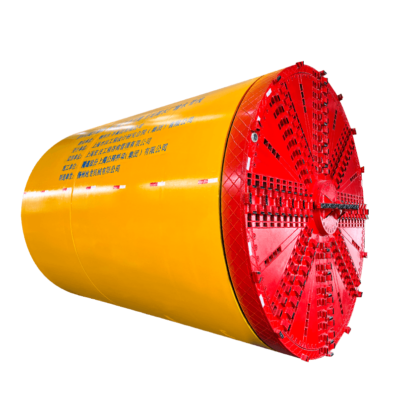
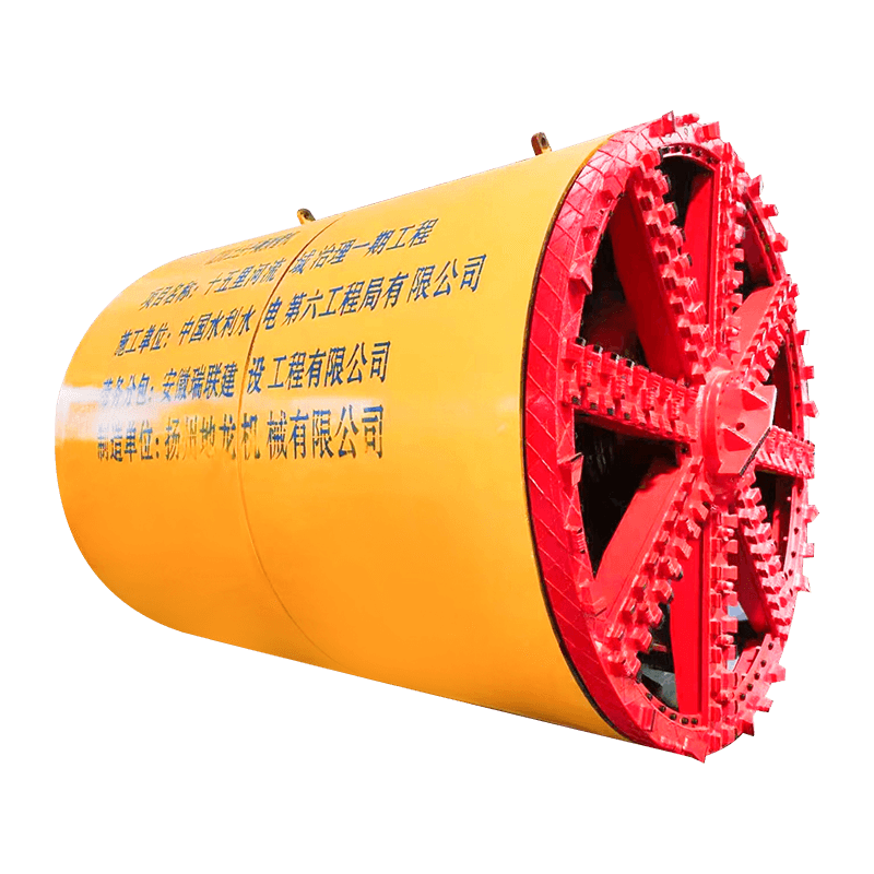
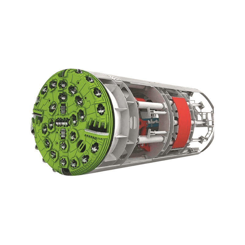
A micro-tunneling machine — commonly abbreviated as MTBM (Micro-Tunnel Boring Machine) — is a remotely operated, pipe-jacking system designed to install underground pipelines without open-cut excavation. The machine bores a precise, controlled tunnel through soil or rock while simultaneously pushing prefabricated pipe sections into the void it creates. The entire operation is directed from a control cabin at the surface, with no workers required inside the tunnel, making it one of the safest and most accurate trenchless installation methods available.
What sets micro-tunneling apart from other trenchless methods like horizontal directional drilling (HDD) or conventional pipe jacking is its level of positional accuracy and its suitability for gravity-flow pipelines. While HDD pulls flexible pipe through a pre-drilled path and accepts a degree of deviation, a micro-tunneling system steers in real time using laser guidance and a steerable cutterhead, achieving line and grade tolerances as tight as ±25mm. This precision makes it the preferred method for sewer, stormwater, and process pipelines where slope must be maintained exactly.
Core Components of a Micro-tunneling System
A complete micro-tunneling system is more than just the cutting machine. It's an integrated assembly of components that work together across the surface and underground to complete the bore safely and accurately. Understanding each part helps explain how the system achieves such reliable results.
The Micro-Tunnel Boring Machine (MTBM)
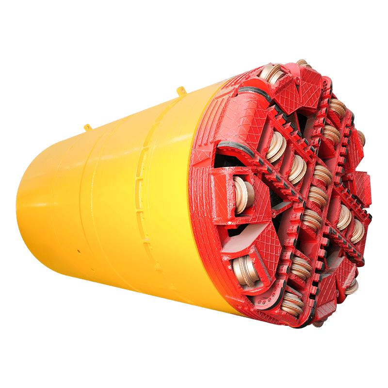
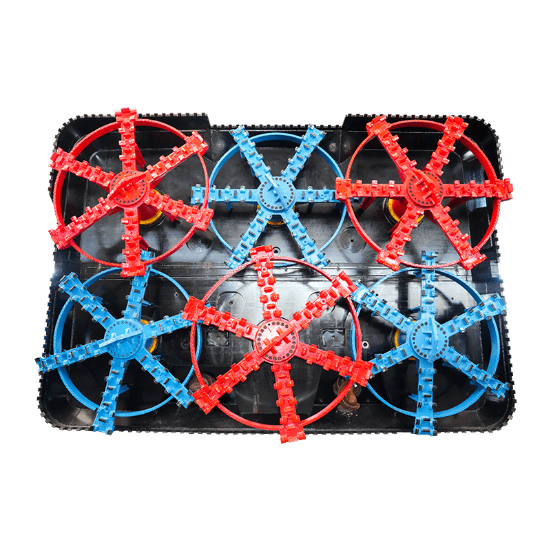
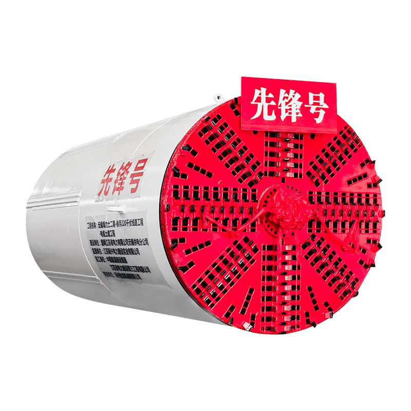
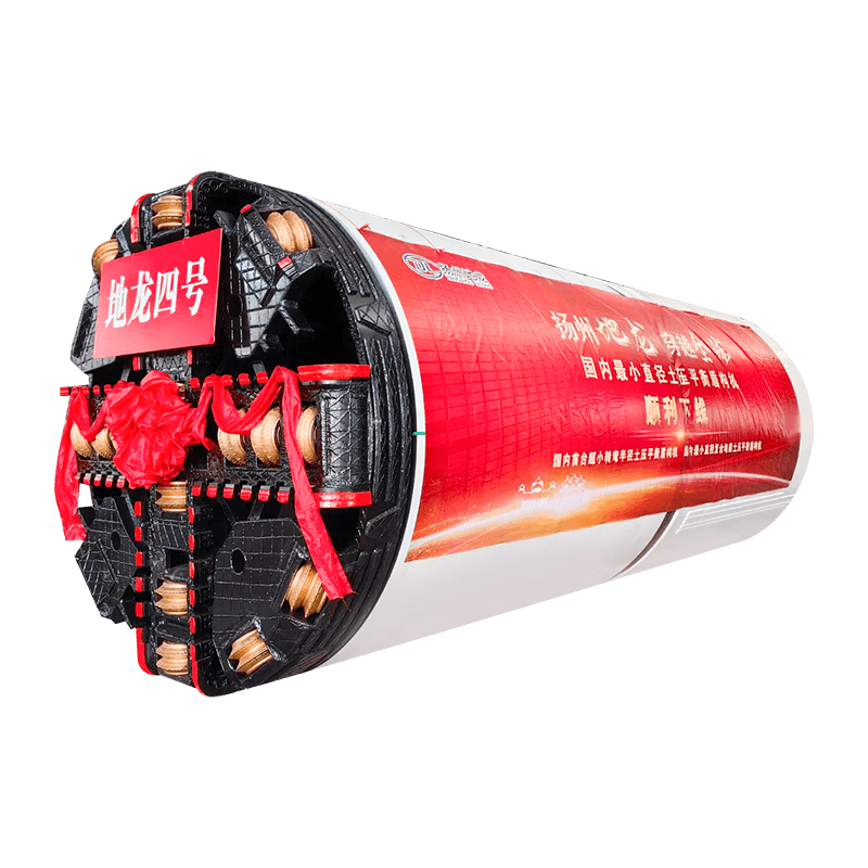
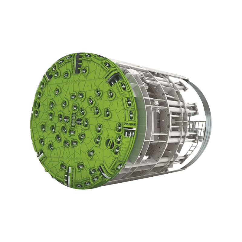
The MTBM itself is the underground cutting unit. It consists of a rotating cutterhead at the front, a slurry chamber directly behind it, and a steerable shield body that contains the hydraulic and electrical drive systems. The cutterhead is selected based on ground conditions — soft ground and mixed face conditions use different cutter configurations than hard rock formations. Behind the shield, the pipe string follows directly, so the machine is always working at the face of the bore while the completed pipeline grows behind it.
The Jacking Frame and Launch Shaft
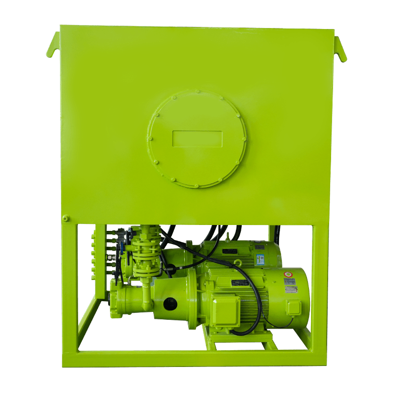
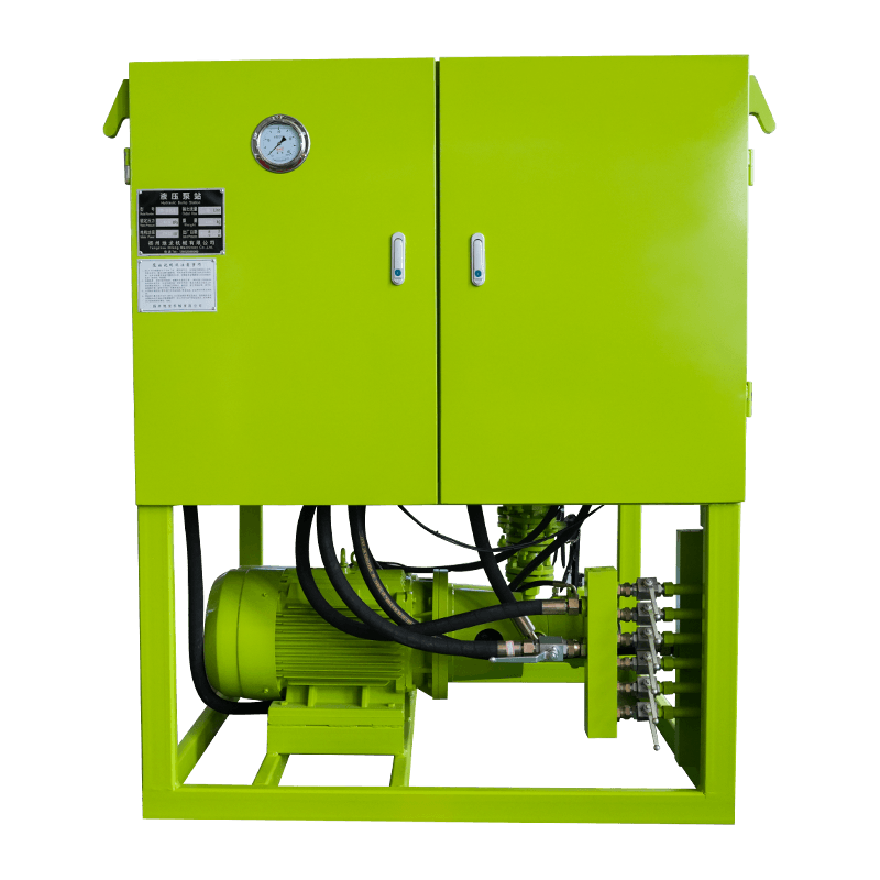
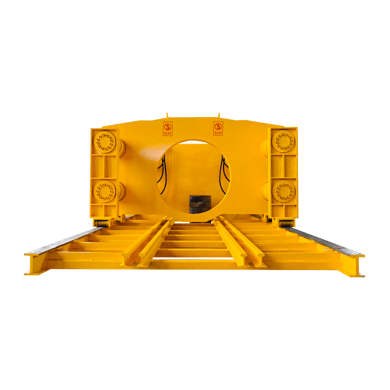
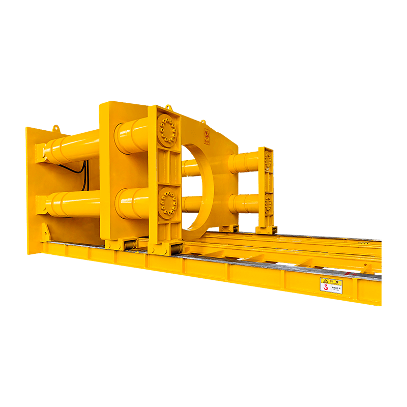
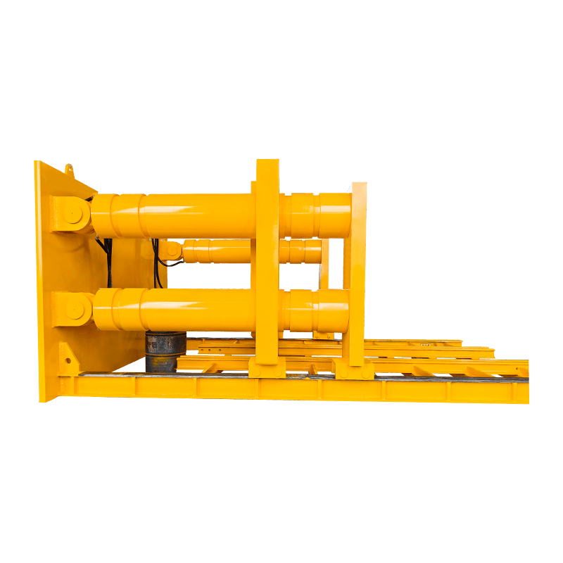
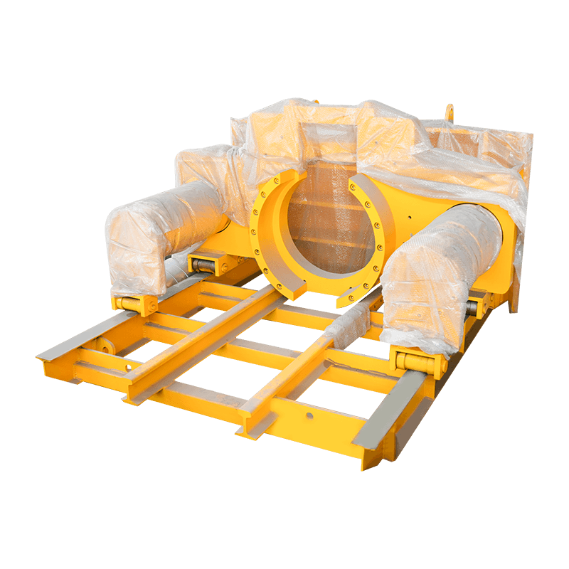
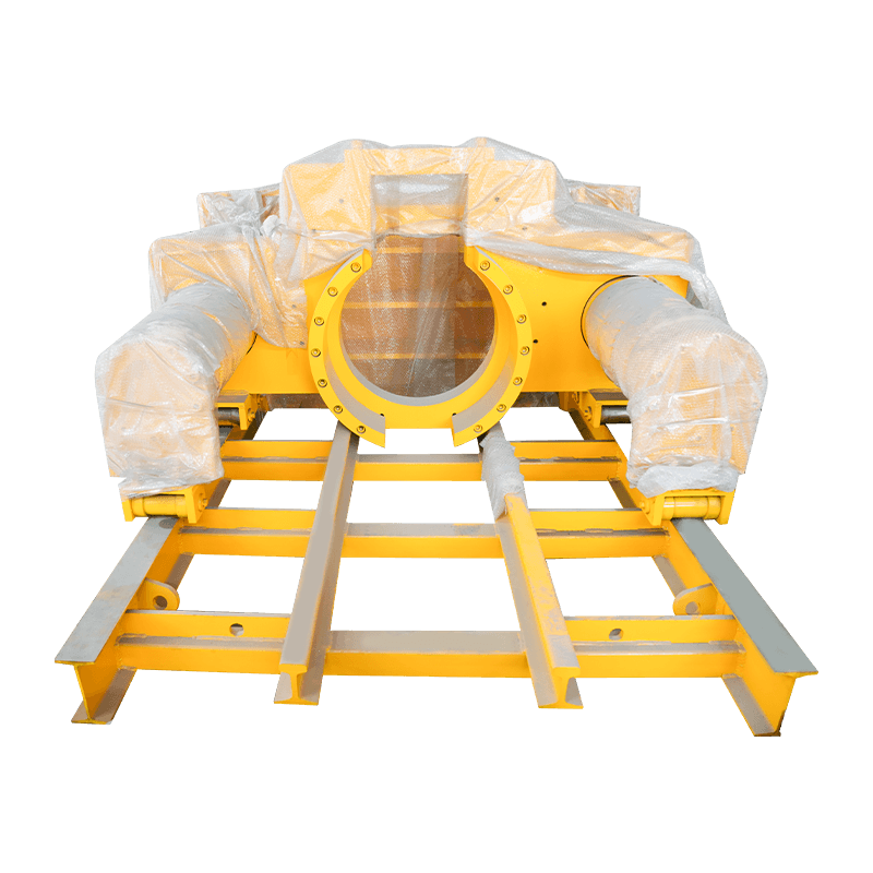
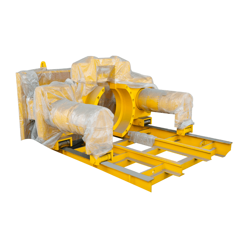
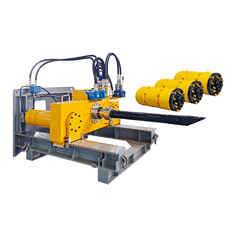
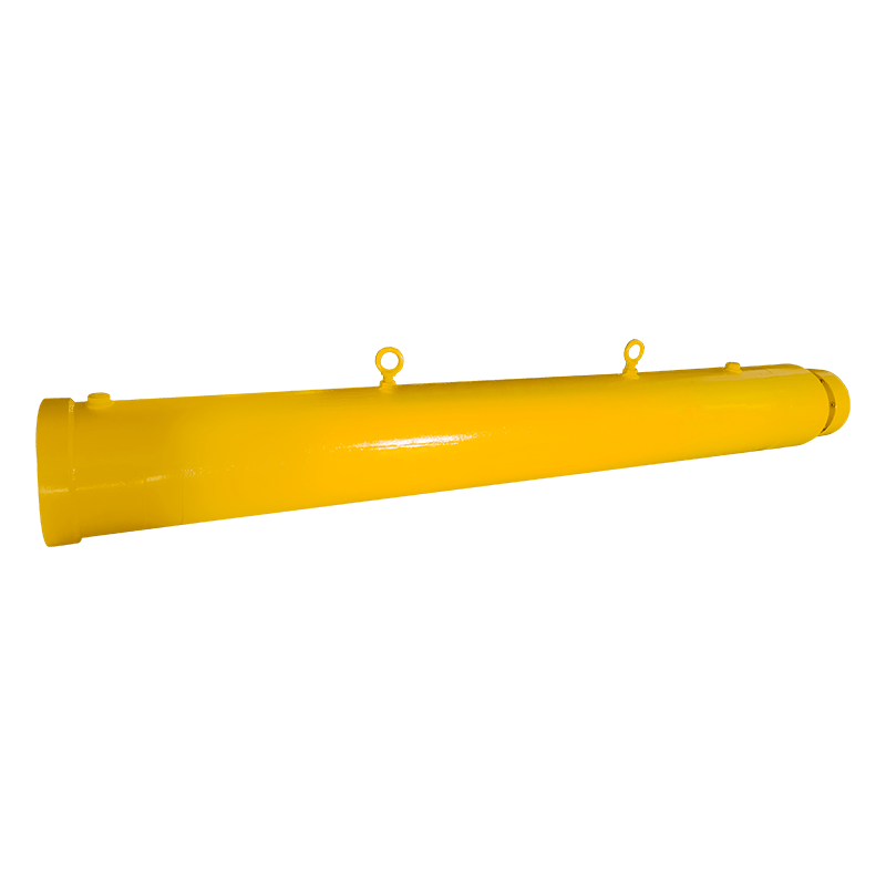
All forward thrust comes from a hydraulic jacking frame installed in a launch shaft at the surface. This frame pushes against a thrust wall and drives the entire pipe string — and the MTBM at its head — forward through the ground. The jacking frame must be sized to handle the maximum anticipated jacking loads for the drive, which can reach several thousand kilonewtons on long or difficult drives. The launch shaft also serves as the staging area where new pipe sections are lowered and added to the string as the bore progresses.
The Slurry Separation Plant
Most micro-tunneling machines use a slurry system to remove excavated material from the face. Pressurized slurry — typically a bentonite and water mixture — is pumped from the surface down to the cutting chamber, where it suspends the spoil and carries it back to the surface through a return line. At the surface, a separation plant processes the returning slurry, removes the soil particles using cyclone separators and vibrating screens, and reconditions the clean slurry for reuse. This closed-loop system controls face pressure, prevents ground settlement, and handles a wide range of soil types efficiently.
The Laser Guidance and Control System
Steering accuracy is achieved through a laser guidance system. A theodolite-mounted laser is set up in the launch shaft, aimed along the design bore line at a target inside the MTBM. Any deviation from the design alignment is detected immediately and displayed at the surface control panel. The operator makes steering corrections by adjusting the extension of articulation cylinders in the MTBM's shield, allowing the machine to be steered back onto line and grade continuously throughout the drive. Modern systems also incorporate gyroscopic sensors for additional positional accuracy on longer or curved drives.
Types of Micro-tunneling Machines by Ground Condition
No single cutterhead design performs equally well across all ground types. Equipment selection is one of the most important decisions in micro-tunneling project planning, and choosing the wrong machine for the ground conditions is a leading cause of project delays and cost overruns. The main categories are:
| Machine Type | Best Ground Conditions | Excavation Method | Spoil Removal |
| Slurry MTBM | Soft soils, sands, gravels, mixed face | Rotating cutterhead with drag bits or disc cutters | Slurry circuit (hydraulic) |
| Rock MTBM | Hard rock, competent formations (UCS >50 MPa) | Disc cutters and roller bits | Slurry or vacuum extraction |
| Auger MTBM | Stable, cohesive soils above groundwater table | Rotating auger flights | Mechanical auger conveyance |
| Vacuum MTBM | Loose, dry soils; urban environments | Cutterhead with vacuum extraction | Vacuum/pneumatic spoil removal |
Mixed-face conditions — where the bore passes through both soil and rock simultaneously — are among the most challenging scenarios in micro-tunneling. Specialized mixed-face cutterheads with both drag bits and disc cutters are available, but they require careful management of face pressure and advance rate to prevent uneven wear or machine rollover in the bore.
When Micro-tunneling Is the Right Choice Over Open-Cut Methods
Open-cut trenching is simpler and cheaper per meter of pipeline installed on greenfield sites with no surface constraints. Micro-tunneling becomes the better option — or the only viable option — when any of the following conditions apply:
- Road and rail crossings: Installing a pipeline beneath an active road, highway, or railway without disrupting traffic is one of the most common applications for micro-tunneling equipment. The bore passes completely beneath the obstruction from shaft to shaft with no surface disturbance.
- River and waterway crossings: Where HDD might risk a frac-out beneath a watercourse, a micro-tunnel boring machine operating under controlled slurry pressure is a more reliable alternative, particularly in urban waterway crossings with limited working space on the banks.
- Deep utility installations: Gravity sewer systems often require pipe installed at depths of 6 to 15 meters or more. At these depths, open-cut excavation requires extensive shoring, dewatering, and traffic management that far exceeds the cost of a micro-tunnel drive.
- Sensitive surface environments: Heritage streetscapes, airport runways, industrial facilities in operation, and environmentally sensitive areas may prohibit open-cut entirely, making trenchless micro-tunneling the only permissible installation method.
- High groundwater or unstable soils: Slurry micro-tunneling machines maintain face pressure that balances groundwater and soil pressure, preventing collapse and minimizing ground movement in soft or waterlogged ground conditions.
Pipe Materials Used with Micro-tunneling Systems
The pipe installed by a micro-tunneling system must withstand not just the service loads it will carry once in operation, but also the significant jacking forces applied during installation. This dual requirement — structural strength and jacking resistance — narrows the field of suitable pipe materials compared to open-cut installation. The most commonly used options are:
- Reinforced Concrete Pipe (RCP): The most widely used pipe type in micro-tunneling for sewer and stormwater applications. Concrete jacking pipe is manufactured with flat, precision-machined steel end rings to distribute jacking loads evenly across the pipe joint. Available in diameters from around 300mm up to 3000mm and beyond.
- Vitrified Clay Pipe (VCP): Highly resistant to chemical attack and widely used for gravity sewer installations. VCP jacking pipe is available in smaller diameters and is particularly favored in corrosive sewer environments where concrete would degrade over time.
- Steel Pipe: Used for pressure pipeline applications, industrial process lines, and casing installations. Steel pipe has excellent jacking force resistance and can be installed in longer drives, but requires cathodic protection or lining in corrosive soil environments.
- Polymer Concrete and GRP Pipe: Glass-reinforced plastic (GRP) and polymer concrete pipes offer high chemical resistance and smooth internal surfaces that maximize hydraulic capacity. They are lighter than concrete but require careful handling to avoid damage to the jacking faces during installation.
Managing Jacking Forces on Long Micro-tunnel Drives
As a micro-tunnel drive gets longer, the friction between the installed pipe and the surrounding soil accumulates, and the total jacking force required to advance the machine increases. On very long drives, this force can exceed the structural capacity of the pipe or the output limit of the jacking frame. Two primary techniques are used to manage this problem on extended drives.
Intermediate Jacking Stations (IJS)
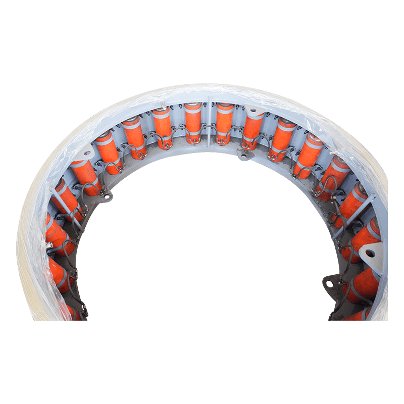
An intermediate jacking station is a hydraulic cylinder assembly built into the pipe string at strategic intervals during installation. When jacking loads approach the pipe's maximum capacity, the IJS is activated to push the forward section of the pipe string and the MTBM ahead independently, while the main jacking frame holds the rear section in place. This effectively breaks the drive into shorter segments from a force management perspective, allowing drives that would otherwise be impossible to complete in a single push. IJS intervals are typically placed every 80 to 150 meters depending on soil friction and pipe capacity.
Lubrication Injection Systems
Most micro-tunnel jacking pipes are equipped with annular lubrication ports — small injection points built into the pipe wall. A bentonite slurry is pumped through these ports under pressure, creating a lubricated annular space between the outer pipe surface and the surrounding soil. This dramatically reduces skin friction and can cut jacking forces by 40 to 70 percent on cohesive soil drives. Maintaining consistent lubrication coverage across the entire pipe string is critical; gaps in lubrication can cause localized friction spikes that are difficult to recover from without the risk of pipe damage.
Key Project Parameters That Affect Micro-tunneling Costs
Micro-tunneling is a premium installation method and carries higher upfront costs than open-cut trenching. Understanding the variables that drive those costs helps project planners make better decisions during the design phase and allows for more realistic budgeting:
- Drive length and diameter: Longer drives and larger pipe diameters require bigger, more powerful equipment and larger launch shafts. Cost per meter generally decreases on longer drives as mobilization costs are spread over more installed pipeline.
- Shaft construction: Launch and reception shafts are a significant cost component, often representing 20–35% of the total drive cost. In urban environments, shaft construction in busy streets requires traffic management, utility diversions, and specialized shoring that adds substantially to the expense.
- Ground conditions: Difficult conditions — cobbles, boulders, mixed face, or high-pressure groundwater — increase machine wear, reduce advance rates, and may require additional interventions that add cost and time to the program.
- Slurry disposal: In environmentally sensitive locations or where treatment facilities are remote, disposing of the contaminated slurry generated during boring can be a significant cost. Some projects require slurry treatment on-site before disposal is permitted.
- Mobilization and equipment transport: Micro-tunneling systems are large, specialized equipment packages. Mobilization from the contractor's yard to site — particularly for remote or international projects — is a fixed cost that needs to be factored into project economics from the start.
Ground Investigation Requirements Before Selecting a Micro-tunneling Machine
Inadequate ground investigation is one of the most common causes of micro-tunneling project failures. The ground conditions directly determine which machine type can be used, what face pressures to apply, how fast the machine will advance, and what risks need to be managed. A thorough geotechnical investigation for a micro-tunneling project should include:
- Borehole drilling at the proposed launch and reception shaft locations, and at regular intervals along the drive alignment, to log soil stratigraphy and retrieve samples for testing.
- Laboratory testing for particle size distribution, plasticity index, unconfined compressive strength (for rock), and abrasion index to assess cutterhead wear potential.
- Groundwater level measurements and permeability testing to establish the face pressure regime required to balance groundwater during boring.
- Identification of any obstructions — abandoned foundations, old culverts, utilities, or boulders — that could interfere with the drive and require pre-treatment or contingency planning.
- Assessment of existing structures and services along the alignment to evaluate settlement sensitivity and determine acceptable ground movement limits that the micro-tunneling machine's face pressure control must stay within.
Advances in Micro-tunneling Technology Worth Knowing About
The micro-tunneling industry has advanced considerably over the past decade, and newer systems offer capabilities that were not available in earlier generations of equipment. Remote monitoring and data logging systems now allow real-time tracking of machine performance parameters — jacking force, face pressure, advance rate, cutterhead torque, and steering position — across multiple drives simultaneously. This data is increasingly used not just for project management but for predictive maintenance, helping operators identify developing equipment issues before they result in unplanned downtime underground.
Curved drive capability has also improved significantly. While early micro-tunneling systems were largely limited to straight drives, modern steerable MTBMs can execute horizontal curves with radii as tight as 150 to 200 meters, opening up alignment options that previously required additional shafts or alternative methods. This capability is particularly valuable in urban environments where pipeline alignments must navigate around existing underground infrastructure. Additionally, advances in mixed-face cutterhead design and wear-monitoring technology have extended the practical range of micro-tunneling into ground conditions that previously required full-face rock tunnel boring machines or manual excavation methods.