

 English
  русский
  عربى
عربى Content
- 1 What an Auger Boring Machine Does and Where It's Used
- 2 How an Auger Boring Machine Works: The Basic Mechanics
- 3 Types of Auger Boring Machines
- 4 Soil Conditions: Where Auger Boring Works and Where It Doesn't
- 5 Auger and Casing Specifications: What to Understand Before You Order
- 6 Launch Pit Requirements and Setup
- 7 Alignment Control and Accuracy in Auger Boring
- 8 Comparing Auger Boring to Other Trenchless Methods
- 9 Key Factors to Evaluate When Selecting an Auger Boring Machine
What an Auger Boring Machine Does and Where It's Used
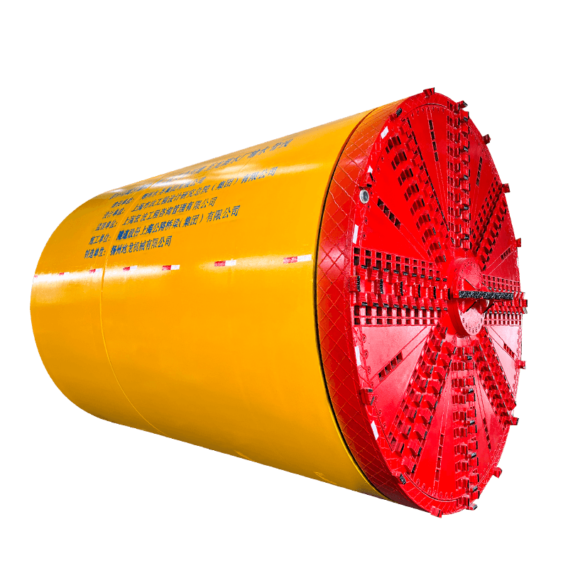
An auger boring machine is a trenchless construction tool designed to install steel casing pipes horizontally through soil without excavating an open trench along the entire installation route. The machine sits inside a launch pit and drives a rotating helical auger — a spiral-bladed shaft — forward through the ground while simultaneously pushing a steel casing pipe behind it. The rotating auger cuts and displaces the soil at the face and carries the excavated material back through the inside of the casing to the launch pit, where it is collected and removed. The result is an installed casing pipe running beneath a road, railway, waterway, or other surface obstruction without disturbing the surface above.
Auger boring is one of the most widely used trenchless installation methods in the utility construction industry. It is the standard approach for installing water mains, gas pipelines, electrical conduits, and telecommunications ducts beneath road crossings, rail lines, and environmentally sensitive areas where open-cut excavation is not permitted or is prohibitively expensive. The method is valued for its relative simplicity, mechanical reliability, and cost-effectiveness across a wide range of soil conditions compared to more complex trenchless technologies such as microtunneling or horizontal directional drilling.
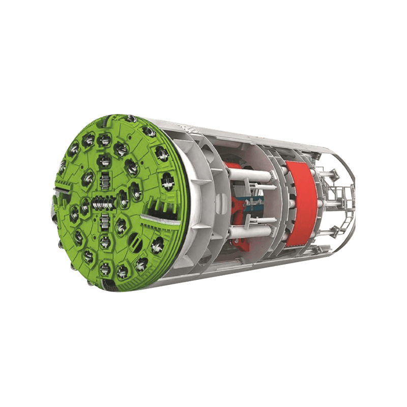
How an Auger Boring Machine Works: The Basic Mechanics
The operating principle of an auger boring machine is straightforward, but understanding it in detail helps clarify both what the machine can do well and where its limitations lie. The process begins in a launch pit excavated to a depth that places the boring machine at the correct elevation for the planned installation. The machine is positioned on steel rails aligned precisely with the required bore direction and grade using laser guidance or optical survey equipment.
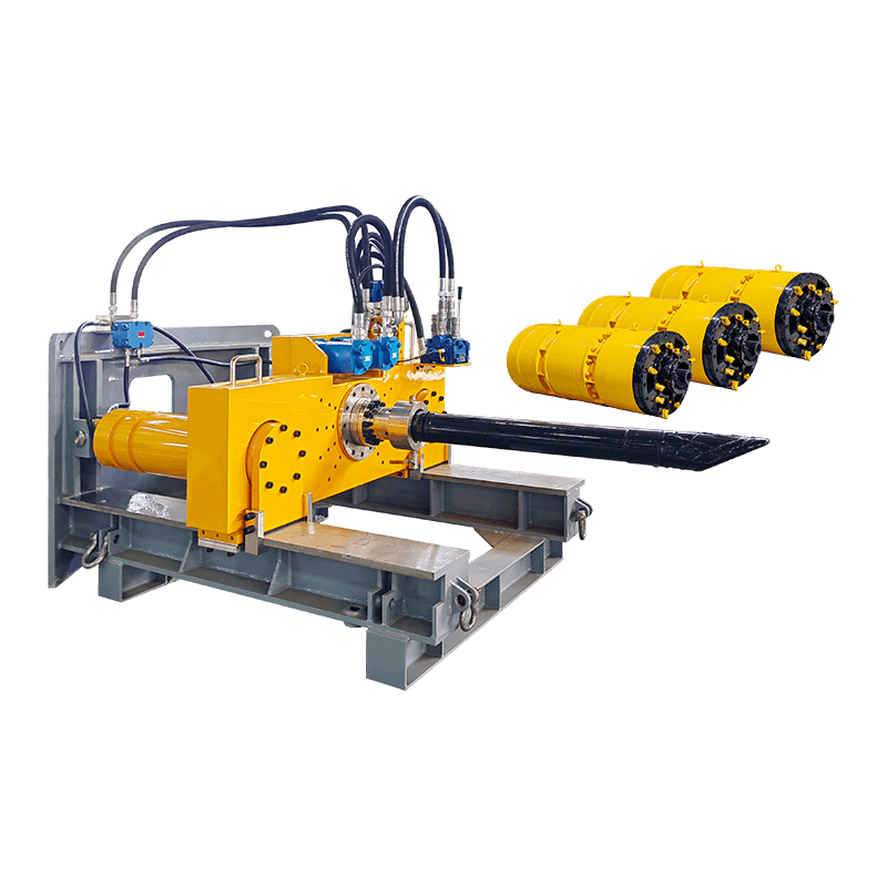
The machine's power unit — typically an electric motor or hydraulic drive system — rotates the auger string through a drive chuck while a hydraulic thrust system pushes the entire auger and casing assembly forward into the soil. The cutting head at the front of the auger string breaks and loosens the soil, and the helical flights of the rotating auger carry the cuttings rearward through the bore hole and back into the launch pit. The steel casing pipe is welded in sections to the rear of the leading pipe as the bore advances, building up the casing string incrementally until the boring machine and auger emerge in the reception pit at the far end of the crossing.
Once the bore is complete, the auger string is withdrawn from the casing, leaving the steel casing pipe permanently in place in the ground. The carrier pipe — the actual utility pipe that will convey the product — is then installed through the casing bore. The casing acts as a protective conduit for the carrier pipe and provides structural support against the soil and surface loads above the crossing. This two-pipe system is a defining characteristic of auger bore construction that distinguishes it from methods where the product pipe is installed directly without a casing.
Types of Auger Boring Machines
Auger boring machines are manufactured in a range of sizes and configurations suited to different installation diameters, soil conditions, and project requirements. Understanding the main categories helps in matching equipment to the specific demands of a project.
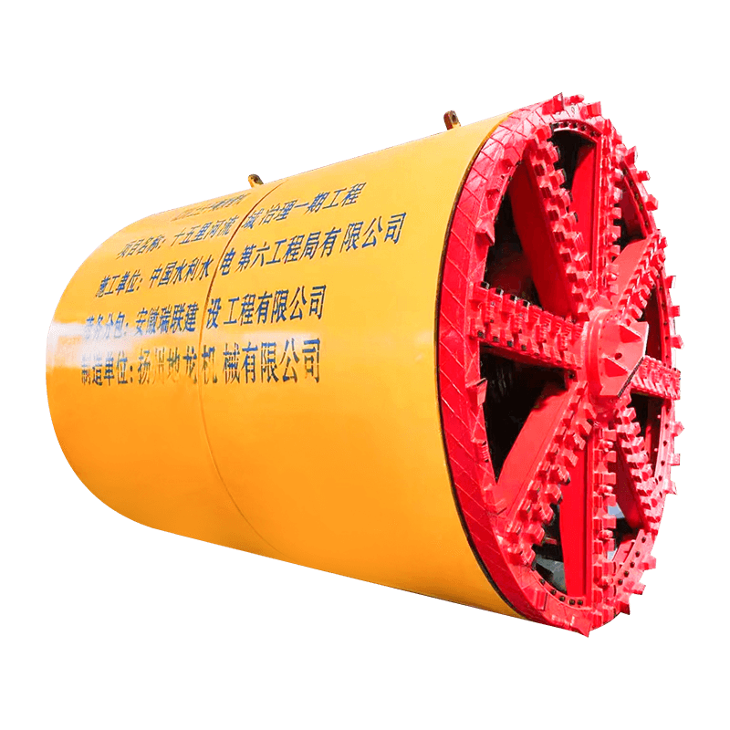
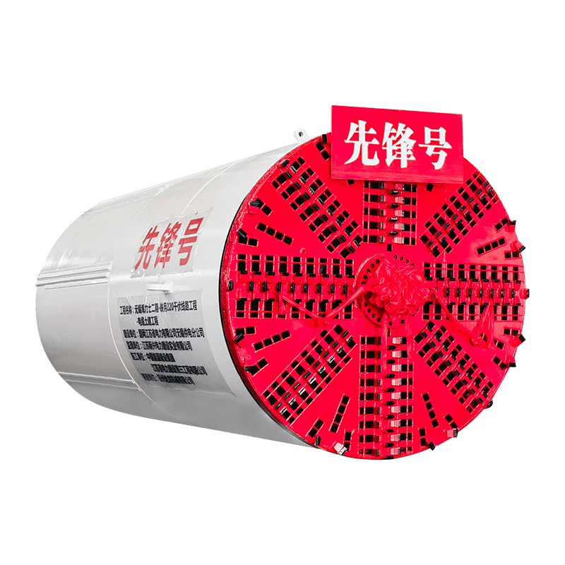
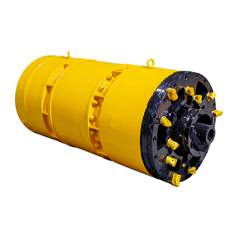
Conventional Auger Boring Machines
Conventional auger boring machines — sometimes called track-mounted or cradle-mounted units — are the standard configuration for most road and utility crossing projects. The machine sits on a steel track frame inside the launch pit and uses a rotary drive head and hydraulic thrust cylinders to advance the auger and casing simultaneously. These machines are available in sizes covering casing diameters from approximately 100mm up to 1500mm or larger, with thrust capacities ranging from 50 tonnes for small-diameter machines to 500 tonnes or more for large-diameter installations. The drive head speed and torque are matched to the casing diameter and soil conditions, with most machines offering variable speed control to optimize cutting performance in different ground types.
Pilot Tube Auger Boring Systems
Pilot tube auger boring is an enhanced version of conventional auger boring that adds a steerable pilot tube installation phase before the full-diameter auger bore. A small-diameter pilot tube is first steered to the reception pit using a theodolite or camera guidance system, establishing a precisely aligned pilot path. The auger boring machine then follows the pilot tube alignment to install the casing pipe at the correct position and grade. This approach achieves significantly tighter installation tolerances — typically within ±25mm of the planned alignment — compared to conventional auger boring, which makes it suitable for applications requiring precise grade control such as gravity sewer installations and crossings with tight clearance requirements beneath existing utilities.
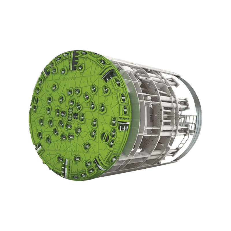
Robotic Auger Boring Machines
Robotic or remotely operated auger boring machines are designed for installations in confined spaces, hazardous environments, or locations where operator presence in the pit is restricted. These machines are controlled from the surface using a remote console and incorporate camera systems and electronic monitoring to allow the operator to manage the bore without being in the launch pit. Robotic auger boring equipment is particularly relevant for crossings in environmentally sensitive areas, contaminated ground, or projects with restricted access that prevent conventional manned pit operation.
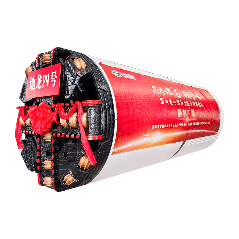
Compact and Skid-Mounted Machines
Compact skid-mounted auger boring machines are designed for smaller-diameter installations — typically 100mm to 600mm casing diameter — in restricted urban environments where pit size and access constraints limit the use of full-sized equipment. These machines have a smaller physical footprint than conventional track-mounted units, require shallower launch pits, and can be moved and set up more quickly between locations. They are commonly used for utility service connections, telecommunications conduit crossings, and smaller water and gas main installations beneath urban roadways where excavation is disruptive and access is limited.
Soil Conditions: Where Auger Boring Works and Where It Doesn't
Soil conditions are the most critical factor determining whether auger boring is the appropriate method for a given crossing and what specific equipment and cutting head configuration will be needed. Auger boring performs well across a wide range of soil types but has specific limitations that must be assessed carefully during project planning.
| Soil Type | Suitability | Typical Cutting Head | Key Considerations |
| Cohesive clay | Excellent | Clay auger / bullet head | Sticky soils may require spoil management; good bore stability |
| Sandy soil | Good | Sand auger / cutter head | Risk of face collapse in dry cohesionless sand; water inflow management needed |
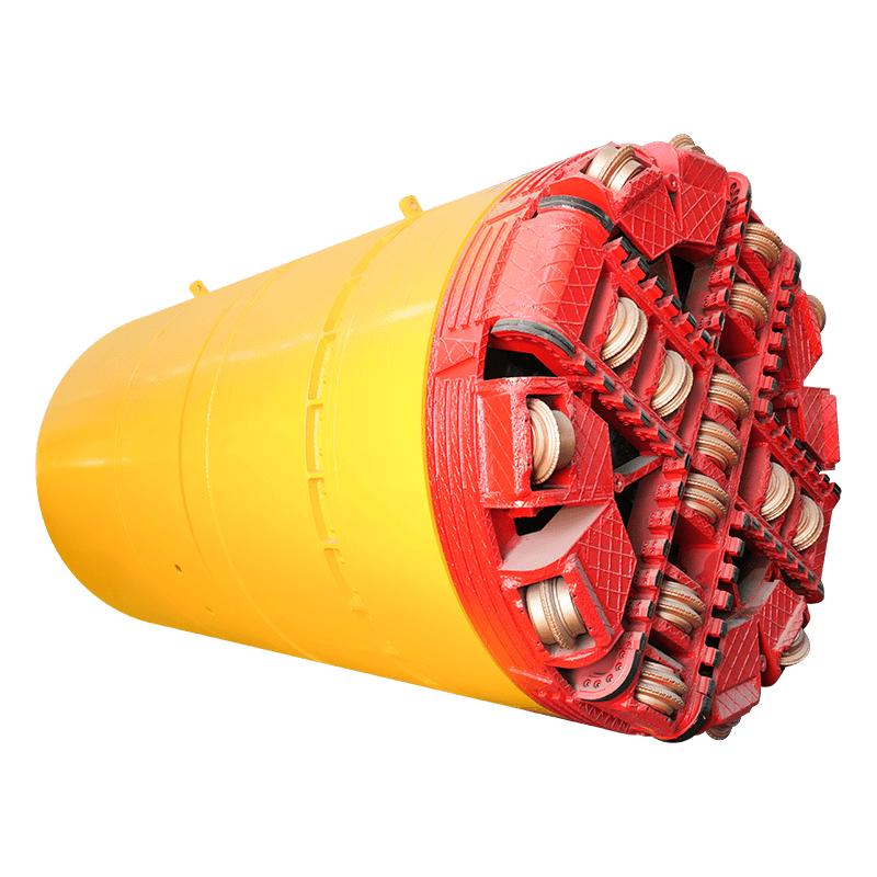
| Gravel and cobbles | Moderate | Rock auger / tungsten carbide tips | Cobbles can cause deviation; oversized auger may be needed |
| Soft rock / weathered rock | Moderate | Rock auger with carbide inserts | High torque demand; auger and cutting head wear rates increase significantly |
| Hard rock | Poor to unsuitable | Not typically used | Torque and thrust demands typically exceed practical machine limits; alternative methods preferred |
| Mixed face (soil and rock) | Challenging | Combination rock/soil head | Variable torque and thrust; increased deviation risk; close monitoring required |
| Saturated loose sand (below water table) | Difficult | Sealed cutting head with pressure control | Ground dewatering or grouting may be required; significant face instability risk |
The most common failure mode in auger boring is deviation from the planned alignment — the bore drifts off line or grade due to soil variability, obstructions, or inadequate machine setup. Cohesive soils with consistent properties are the most forgiving in terms of maintaining bore direction. Granular soils, mixed face conditions, and any ground containing boulders or cobbles significantly increase deviation risk and require more rigorous alignment monitoring throughout the bore.
Auger and Casing Specifications: What to Understand Before You Order
The auger and casing specifications are the technical parameters that define what an auger boring machine can install and how it will perform in specific ground conditions. Getting these specifications right is fundamental to a successful installation — undersized augers lack the torque capacity for the soil conditions, and casing that is not matched to the machine's thrust capacity will buckle or stall the bore before completion.
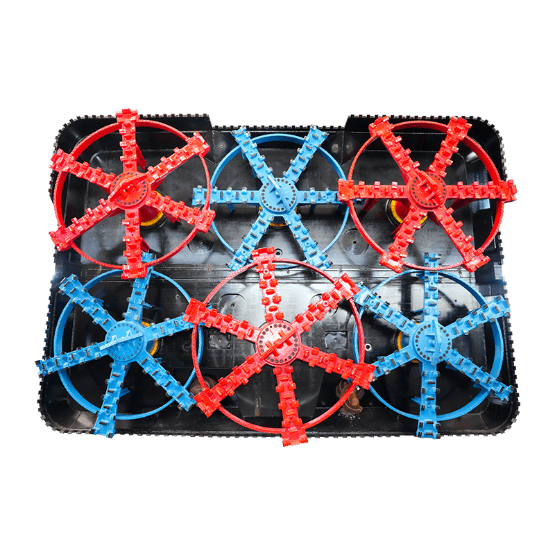
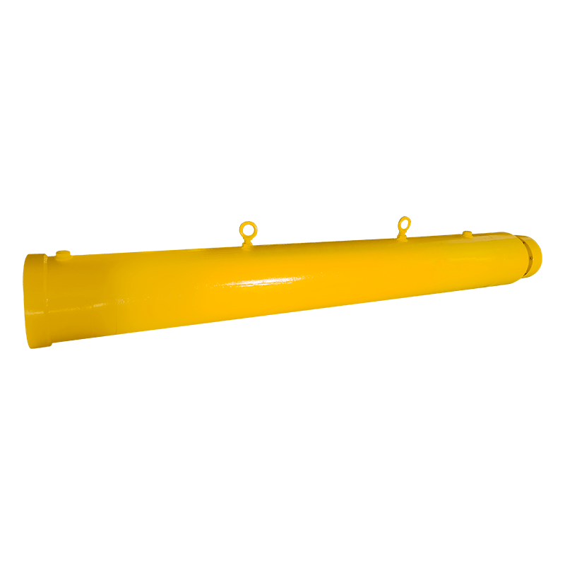
Auger Flight Design and Diameter
The auger flights — the helical blades wrapped around the central shaft — must be sized to run inside the casing diameter with sufficient clearance to convey cuttings rearward without jamming. Standard auger outside diameters are typically 10–25mm smaller than the nominal casing inside diameter, providing an annular space for cuttings transport. Flight pitch — the distance between successive helix turns — affects how efficiently cuttings are moved along the auger. Closer pitch is more effective in loose, flowing soils; wider pitch handles sticky cohesive soils better by reducing the tendency for clay to pack in the flights and cause blockages.
Auger Shaft Torque Capacity
The auger shaft must be capable of transmitting the rotational torque required to cut the soil and transport the cuttings back to the launch pit without twisting or failing. Torque demand increases with bore diameter, soil strength, casing length, and the depth of soil cover above the bore. For long bores in stiff soils, the cumulative torque demand on the auger shaft — which must overcome both the cutting resistance at the face and the friction of the cuttings along the entire length of the bore — can be very substantial. Auger boring machine manufacturers publish torque ratings for their equipment in specific soil conditions, and these should be compared against a geotechnical assessment of the expected torque demand before equipment selection is finalized.
Casing Wall Thickness and Grade
Steel casing pipe for auger bore installations must have sufficient wall thickness to resist the compressive thrust force applied by the boring machine without buckling, and sufficient structural capacity to support the soil and surface loads applied after installation. Minimum wall thickness for auger bore casing is typically determined by the installation thrust requirement, with API 5L or equivalent structural steel grades commonly specified. For crossings beneath heavy highway or rail loading, additional wall thickness calculations based on the permanent service load conditions are required. Casing joints are typically butt-welded in the pit during installation, and weld quality directly affects the structural integrity of the completed casing string under both installation and service loads.
Launch Pit Requirements and Setup
The launch pit is the working platform from which the auger boring machine operates, and its design and construction are as important to the success of the installation as the machine itself. An inadequately sized or poorly constructed launch pit is one of the most common causes of problems during auger bore construction — an unstable pit wall can collapse and block the bore, and a pit that is too short prevents full machine stroke utilization, reducing installation efficiency.
- Pit length: The launch pit must be long enough to accommodate the boring machine length plus the length of one casing pipe section plus working space for the operator and equipment. A minimum pit length of machine length plus 1.5–2 times the casing pipe joint length is the general planning rule, though specific machine requirements and casing lengths vary. Longer pits allow more efficient operation by maximizing each push stroke before stopping to add a new casing section.
- Pit width: The pit width must allow the machine to be positioned on its track frame with sufficient clearance on each side for access and operation. A minimum working clearance of 600mm on each side of the machine frame is typically required, with additional width needed for casing handling, spoil removal, and safety compliance. The pit should also be wide enough to allow emergency egress for workers in the event of ground movement or equipment failure.
- Pit depth and machine elevation: The pit depth is determined by the required installation depth of the casing centerline. The machine must be positioned at the elevation that places the bore at the correct depth and grade, accounting for the machine's own height above the pit floor. Precise elevation setting of the machine on its launch frame is critical — any error in machine elevation translates directly into an error in the final installation depth that cannot be corrected once boring has commenced.
- Pit support and shoring: Launch pits must be shored or supported to prevent wall collapse during machine operation. The vibration generated by the boring machine, combined with the surcharge load from the machine weight on the pit wall, creates conditions that can destabilize unsupported excavations even in stable ground. Steel sheet piling, trench boxes, or engineered timber shoring are the standard support methods, and the shoring design must account for the reaction force generated by the boring machine's thrust system pushing against the pit headwall.
- Thrust wall construction: The boring machine's hydraulic thrust cylinders push against a thrust wall at the rear of the launch pit — typically a reinforced concrete structure or a steel plate bearing system designed to distribute the thrust force into the surrounding ground. The thrust wall must be capable of resisting the full rated thrust capacity of the boring machine without movement or failure. Any movement of the thrust wall during boring causes the machine to shift from its alignment, potentially causing bore deviation that cannot be corrected.
Alignment Control and Accuracy in Auger Boring
Maintaining the planned horizontal and vertical alignment throughout an auger bore is one of the primary technical challenges of the method. Unlike steerable trenchless methods such as horizontal directional drilling or microtunneling, conventional auger boring has no active steering mechanism — once the bore begins, any deviation from the planned line and grade cannot be corrected during that bore. This makes pre-bore setup accuracy and real-time monitoring during boring critical to achieving an acceptable installation.
Machine alignment is set before boring commences using a laser level or optical survey instrument positioned in the launch pit. The laser beam defines the planned bore centerline, and the machine's drive head is aligned to match it using adjustable support jacks on the track frame. The accuracy of this initial setup directly determines the achievable installation tolerance — a well-set machine in good ground conditions can achieve horizontal and vertical accuracy within ±50mm over typical road crossing lengths of 20–40 meters with conventional boring equipment, and within ±25mm with pilot tube guidance systems.
During boring, alignment is monitored by tracking the position of the cutting head or the leading casing pipe using a camera system, survey instruments, or a target mounted in the bore and observed through a transit. Any deviation detected should trigger a review of the possible causes — soil variability, obstructions, machine vibration effects — before continuing. In most conventional auger boring applications there is limited ability to correct deviation once it has occurred, which is why early detection and a decision to abandon and redesign the bore before excessive deviation accumulates is often more cost-effective than continuing a bore that has already deviated significantly from tolerance.
Comparing Auger Boring to Other Trenchless Methods
Auger boring is one of several trenchless installation methods available for utility crossings, and the choice between methods depends on factors including installation diameter, crossing length, soil conditions, accuracy requirements, and project budget. Understanding how auger boring compares to the main alternatives helps in making an informed method selection during project planning.
- Auger boring vs. Horizontal Directional Drilling (HDD): HDD uses a steerable drill string and fluid-assisted excavation to install pipes along a curved profile, allowing both horizontal and vertical curves in the installation path. HDD is more flexible in terms of installation geometry and can achieve greater crossing lengths than auger boring. However, HDD requires more specialized equipment and expertise, is less effective in cohesive clays that do not interact well with drilling fluid, and does not install a steel casing — the product pipe is pulled directly. Auger boring is generally more cost-effective for shorter, straight crossings in cohesive soil where the steel casing is required by design or specification.
- Auger boring vs. Microtunneling: Microtunneling uses a remotely operated tunneling machine with active steering capability, continuous spoil removal via slurry pipeline, and real-time position monitoring to install pipes to very high alignment tolerances — typically ±10–25mm. It is suitable for large-diameter installations, long crossings, and applications requiring precise grade control such as gravity sewer installations. The trade-off is significantly higher equipment cost and operational complexity compared to auger boring. Auger boring is preferred where the installation tolerances can be met with conventional equipment and the crossing length and diameter are within the practical range of the method.
- Auger boring vs. Pipe Ramming: Pipe ramming drives a steel casing through the ground using a pneumatic impact hammer rather than a rotating auger. It requires no launch pit machinery beyond the impact hammer, is faster to set up, and can handle some ground conditions — particularly those with boulders or cobbles — that cause problems for auger boring. The limitation is that pipe ramming provides no active soil removal during installation — the soil is compressed around the casing rather than excavated — which can cause surface settlement and is not appropriate in all ground conditions. Auger boring's continuous soil removal through the auger flights reduces the risk of surface settlement compared to pipe ramming, making it preferable in sensitive surface environments.
Key Factors to Evaluate When Selecting an Auger Boring Machine
Selecting the right auger boring machine for a project requires matching the machine's capabilities to the specific installation requirements in a way that provides sufficient capacity for the expected conditions without unnecessarily oversizing equipment that increases mobilization cost. The following factors represent the essential specification parameters to evaluate during equipment selection.
- Maximum casing diameter and bore diameter range: The machine must be capable of driving the required casing diameter through the soil conditions present. Confirm that the machine's drive chuck, track frame width, and auger capacity cover the full range of diameters required across the project, including any variation between different crossings on the same contract.
- Maximum thrust force: The machine's thrust capacity must exceed the expected maximum installation thrust, which is calculated based on casing diameter, crossing length, soil friction parameters, and any obstructions anticipated along the bore path. Apply a minimum factor of safety of 1.5 to the calculated installation thrust when selecting machine thrust capacity to account for variability in soil conditions and unexpected resistance.
- Torque output and speed range: The drive head torque must be sufficient to rotate the auger string against the cutting resistance and cuttings transport friction throughout the full bore length. Variable speed control allows the operator to optimize rotational speed for different soil types and conditions as the bore progresses through variable ground.
- Stroke length: The machine's hydraulic stroke length determines how much casing is advanced per push cycle. Longer stroke machines advance more casing per cycle and require less frequent stops to add new casing sections, improving production rates. Match the stroke length to the available pit length and the joint length of the casing pipe being installed.
- Power supply requirements: Confirm whether the machine operates on electric, hydraulic, or diesel power and that the required power supply is available at the project site. Electric-powered machines are preferred in confined urban areas for noise and emission reasons but require an adequate power supply connection. Diesel-powered machines are more self-contained but generate exhaust and noise that may require mitigation in sensitive environments.
- Guidance system compatibility: Confirm whether the machine is compatible with the guidance system required by the project specification — laser, optical, camera, or pilot tube guidance — and that the required accuracy is achievable with the selected machine and guidance combination in the expected ground conditions.


